Weldability of Steels
Weldability of Steels
There are several factors which control the weldability of carbon (C) and low alloy steels in electric arc welding. A good understanding of the chemical and physical phenomena which occurs in the weldments is necessary for the proper welding of the different steels. Operational parameters, thermal cycles, and metallurgical factors affecting the weld metal transformations and the susceptibility to hot and cold cracking are some of the factors which have marked influence on the weldability of steels. There are also some common tests which determine the weldability of steel.
The C and low alloy steels represents a large number of steels which differ in chemical composition, strength, heat treatment, corrosion resistance, and weldability. These steels can be categorized as (i) plain C steels, (ii) high strength low alloy (HSLA) steels, (iii) quenched and tempered (QT) steels, (iv) heat treatable low alloy (HTLA) steels, and (v) pre-coated steels.
To understand weldability of steels, it is necessary to have knowledge about the various weld regions.
Characteristic features of welds
Single pass weldments
In the case of a single pass bead, the weldment is generally divided into two main regions namely (i) the fusion zone, or weld metal, and (ii) the heat affected zone (HAZ) as shown in Fig 1. Within the fusion zone, the peak temperature exceeds the melting point of the base steel, and the chemical composition of the weld metal depends on the choice of welding consumables, the base steel dilution ratio, and the operating conditions. Under conditions of rapid cooling and solidification of the weld metal, alloying and impurity elements segregate extensively to the centre of the inter-dendritic or inter-cellular regions and to the centre parts of the weld, resulting in significant local chemical in-homogeneities. Therefore, the transformation behaviour of the weld metal can be quite different from that of the base steel, even when the bulk chemical composition is not significantly changed by the welding process. The typical anisotropic nature of the solidified weld and structure is also shown in Fig 1.
The chemical composition remains largely unchanged in the HAZ region since the highest temperature remains below the melting point of the base steel. However, considerable microstructural change takes place within the HAZ region during welding as a result of the extremely severe thermal cycles. The material immediately adjacent to the fusion zone is heated high into the austenitic temperature range. The micro-alloy precipitates which has developed in the previous stages of processing get generally dissolved and unpinning of austenite grain boundaries occurs with substantial growth of the grains, forming the coarse grain in the HAZ region. The average size of the austenite grains, which is a function of the highest temperature attained, decrease with increasing distance from the fusion zone. The cooling rate also varies from point to point in the HAZ region. It increases with increasing highest temperature at constant heat input and decreases with increasing heat input at constant highest temperature. Because of varying thermal conditions as a function of distance from the fusion line, the HAZ region is essentially composed of coarse grain zone (CGHAZ), fine grain zone (FGHAZ), inter-critical zone (ICHAZ), and subcritical zone (SCHAZ). The various HAZ regions of a single pass low C steel butt weld are shown in Fig 1.
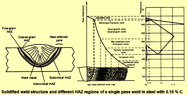
Fig 1 Weld structure and HAZ regions in a single pass low C steel but weld
Multi pass weldments
The situation in the multi pass weldments is much more complex because of the presence of reheated zones within the fusion zone (Fig 2). The partial refinement of the microstructure by subsequent weld passes increases the inhomogeneity of the various regions with respect to the microstructure and the mechanical properties. Re-austenitization and subcritical heating can have a profound effect on the subsequent structures and properties of the HAZ region. Toughness property deterioration is related to small regions of limited ductility and low cleavage resistance within the CGHAZ which are identified as the localized brittle zone (LBZ). LBZs consist of unaltered CGHAZ, inter-critically reheated coarse grain (IRCG) HAZ, and sub-critically reheated coarse grain (SRCG) HAZ. LBZs can be aligned at an adjacent fusion line (Fig 2). The aligned LBZs offer short and easy paths for crack propagation. Fracture occurs along the fusion line.
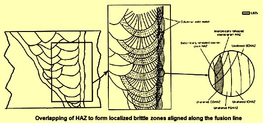
Fig 2 Overlapping of HAZ to form localized brittle zones aligned along the fusion line
Metallurgical factors affecting weldability
The metallurgical factors which affect the weldability are described below.
Hardenability
Hardenability in steels is generally used to indicate austenite stability with alloy additions. It is also being used as an indicator of weldability and as a guide for selection a material and welding process to avoid excessive hardness and cracking in the HAZ region. Steels with high hardness often contain a high volume fraction of martensite, which is exceedingly susceptible to cracking during the processing. Hardenability is also used to indicate the susceptibility of steel to hydrogen (H2) induced cracking. Traditionally, empirical equations have been developed experimentally to express weldability of steels. Carbon equivalent (CE) is one such terminology. It has been developed to estimate the cracking susceptibility of a steel during welding and to determine whether the steel needs pre-weld or/and post-weld heat treatments to avoid cracking. CE equations include the hardenability effect of the alloying elements by expressing the chemical composition of the steel as a sum of weighted alloy contents. Many CE terminologies with different coefficients for the alloying elements are being used. The equation for the CE as given by the ‘International Institute of Welding (IIW)’ is given below.
CE = C + Mn/6 + (Ni + Cu)/15 + (Cr + Mo + V)/5
In this equation the concentration of the alloying elements is given in weight percent. It can be seen in the equation that C is the element which has maximum effects on the weldability. Along with other chemical elements, C can affect the solidification temperature range, hot tear susceptibility, hardenability, and cold cracking behaviour of the steel weldment.
The application of CE terminologies is also empirical. As an example, the CE equation of IIW has been used effectively with usual medium C low alloy steels. Steels with lower CE values generally show good weldability. When the CE of the steel is less than 0.45 %, weld cracking is unlikely, and no heat treatment is needed. When the CE of the steel is between 0.45 % and 0.60 %, weld cracking is likely to take place, and preheating in the range of around 100 deg C to 400 deg C is generally suggested. When the CE of the steel is more than 0.60 %, there is a high probability for the weld to crack, and in such case both preheating and the post-weld heat treatments are needed to get a sound weld.
However, the CE equation of IIW does not accurately correlate with the microstructures and properties of low C micro-alloyed steels over extended alloy ranges. Thus, new terminologies based on solution thermodynamics and kinetic considerations have been developed to obtain better predictions of the alloy behaviour and weldability of low C low alloy steels. Complex interactive terms, rather than simple additive forms, are included in these equations. Equations with these nonlinear terms are more useful in predicting electric arc welding behaviour.
Several terminologies are also available for other steel groups with a wider range of alloying elements and with different prior heat treatments, H2 contents, and weld hardnesses. One such equation (given below) includes fabrication conditions such as heat input, cooling rate, joint design and restraint conditions have also been proposed.
Ph = Pcm + 0.075 log10 H + Rf /40,000
In this equation Ph is the cracking susceptibility parameter, H is the concentration of H2 (in parts per million, ppm), Rf is the restraint stress (in N/sq mm), and Pcm is as per the following equation.
Pcm= C + (Mn + Cu + Cr) /20 + Si/30 + Ni/60 + Mo/15 + V/10 + 5 B
The thickness of the steel being welded can also be related to CE as a compensated carbon equivalent (CCE) which is CCE = CE + 0.00254 t where t is the thickness of the part in millimeters.
The above equations are valid only for specific ranges of chemical composition and welding conditions. However, despite the different forms and terms included in the predictive equations, the main objective remains that of estimating the weldability and cracking susceptibility of the steel.
Weld metal microstructure
Inherent in the welding process is the formation of a pool of liquid steel directly below a moving heat source. The shape of this liquid pool is determined by the flow of both heat and metal, with melting occurring ahead of the heat source and solidification occurring behind it. Heat input determines the volume of liquid steel and therefore the dilution and weld metal composition, as well as the thermal conditions under which solidification takes place. Also important to solidification is the crystalline growth rate, which is geometrically related to weld travel speed and weld pool shape. Thus, weld pool shape, weld metal composition, cooling rate, and growth rate are all the factors which are interrelated with heat input, which in turn affects the solidification microstructure and the tolerance of the weldment to hot cracking.
Incipient melting at base steel grain boundaries immediately adjacent to the fusion zone allows these grains to serve as seed crystals for epitaxial ( an oriented overgrowth of crystalline material upon the surface of another crystal of different chemical composition but similar structure) grain growth during weld metal solidification. The continuous growth of the epitaxial grains results in large columnar grains whose boundaries provide easy paths for crack propagation. An elongated weld pool yields straight and broad columnar grains, which promote the formation of centerline cracking because of impurity segregation, mechanical entrapment of inclusions, and the shrinkage stresses which develop during solidification. Epitaxial columnar growth is particularly harmful in multi-pass welds where grains can extend continuously from one weld bead to another.
Hot tears originate near the liquid / solid interface when strains from solidification shrinkage and thermal contraction cause rupture of the liquid films of low melting point located at grain boundaries. The susceptibility of steel to hot tearing is related to its inability to accommodate strain through dendrite interlocking as well as the tendency of tears to backfill with the remaining liquid. The time interval during which liquid films can exist in relation to the rate of strain generation can also play a role in hot tear susceptibility. Steels can be hot tear sensitive depending on the amount of phosphorus (P) and sulphur (S) impurities they contain. C and nickel (Ni) are also known to influence hot cracking in steel welding.
When the solidified steel weld metal cools down, solid state transformation reactions can occur. As in solidification, the two main factors which determine the final microstructure are the chemical composition and thermal cycle of the weld metal. In maximum structural steels, weld metal solidifies as delta – ferrite. At the peritectic temperature, austenite forms from the reaction between liquid weld metal and delta – ferrite, and subsequent cooling leads to the formation of alpha – ferrite. During the austenite to ferrite transformation, proeutectoid ferrite forms first along the austenite grain boundaries. This is known as grain boundary ferrite. Subsequent to grain boundary ferrite formation, ferrite side plates develop in the form of long needlelike ferrite laths that protrude from the allotriomorphs. A coarse austenite grain size and low C content, in combination with a relatively high degree of super cooling, are found to promote ferrite side plate formation. These laths can be properly characterized by their length to width aspect ratios (usual values are more than 10:1).
As the temperature continues to drop, intra-granular acicular ferrite nucleates and grows in the form of short laths separated by high angle boundaries. The inclination between orientations of adjacent acicular ferrite laths is usually larger than 20 degrees. The random orientation of these laths provides good resistance to crack propagation. Acicular ferrite laths have aspect ratios ranging from 3:1 to 10:1.
During proeutectoid ferrite formation, C is rejected continuously from the ferrite phase, enriching the remaining austenite, which later transforms into a variety of constituents, such as martensite (both lath and twinned), bainite, pearlite, and retained austenite. Because of the acicular nature of the bainite laths, they can also be described by their aspect ratio, with values similar to those of Widmanstätten side-plates. Very frequently, however, bainite laths occur in the form of packets associated with grain boundaries.
HAZ microstructure
In terms of microstructure, long bainite laths with alternate layers of connected martensite islands are generally found in the CGHAZ of HSLA steel weldments. Martensite islands (martensite retained austenite constituents) are formed because of the enrichment of C in austenite in the inter-critical zone. Coarse austenite grain size in the near fusion region of the HAZ can suppress high temperature transformation products in favour of martensite and bainite on cooling. Upper bainite has a relatively high transformation temperature and is stable relative to the thermal cycles subsequent to those of the first pass. Fluctuation of the chemical composition of the micro-alloying elements can also contribute to CE change and to the amount of hard martensite present in the CGHAZ.
In the case of FGHAZ, even though the peak temperature attained is above thermal cycle Ac3, it is still well below the temperature for grain coarsening. The smaller prior austenite grain size and subsequent ferrite transformation produce a refined microstructure having grains smaller than those of the base steel. The microstructure is similar to that of normalized steel, with considerable toughness.
In case of ICHAZ, only partial transformation takes place resulting in a mixture of austenite and ferrite at the peak temperature of the thermal cycle. Upon cooling, the austenite in a matrix of soft ferrite decomposes, and the final microstructure depends on the bulk and local composition of the alloying elements. The cooling rate is also an important factor in determining the amount of martensite and bainite in the ferrite matrix.
In the case of SCHAZ, no observable microstructural changes are observed. Some spheroidization of carbides can occur. Upon reheating by subsequent weld passes, precipitates or pre-precipitate clusters can form, reducing the toughness. Irregularly shaped particles can also coalesce and strain the surrounding matrix, further lowering the toughness.
During HAZ thermal cycles between Ac1 and Ac3, the austenite gets enriched with C, which, upon cooling, transforms to martensite islands. In the as-welded condition, this transformation affects the IRCG region more than the other reheated zone.
Effect of chemical composition
The presence of a certain phase in the final microstructure of a weldment is generally explained by means of a continuous cooling transformation (CCT) diagram, which is formed by two sets of curves namely (i) the percent transformation curves, and (ii) the cooling curves. The percent transformation curves define the regions of stability of the different phases. The cooling curves represent the actual thermal conditions that the weld experienced. The intersection of these two sets of curves determines the final microstructure of the different weld zones. Typical CCT diagram for an HSLA steel weld metal is given in Fig 3.
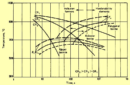
Fig 3 CCT diagram for an HSLA steel weld metal
Hardenability elements, such as C, manganese (Mn), chromium (Cr), and molybdenum (Mo), suppress the start of austenite decomposition to lower temperatures. This is equivalent to pushing the transformation curves to the right side of the CCT diagram, resulting in a refined microstructure. Inclusion formers, such as oxygen (O2) and S, accelerate the austenite to ferrite transformation by providing more nucleation sites for the reaction to initiate at higher temperatures. Faster cooling has the same effect as an increase in hardenability elements, while a slower cooling rate acts in the same direction as a decrease in hardenability agents or an increase in nucleation site providers. Since the cooling rate varies from point to point in the HAZ, the microstructure also changes accordingly, with martensite and bainite in regions close to the fusion line.
Pre-weld and post-weld heat treatments
In the welding of C and low alloy steels, the final microstructure of the weldment is primarily determined by the cooling rate from the peak temperature. Since the alloy level in C and low alloy steels is low, the main physical properties of the steel are not affected. Thus, temperature gradient and heat input become the important parameters in weld metal microstructural evolution. A slower cooling rate decreases shrinkage stress, prevents excessive hardening, and allows time for H2 diffusion. Cooling rate is mainly important and is a function of the difference in temperature as well as the thermal conductivity of the steel.
During preheating, the initial temperature of the steel plate increases, decreasing the cooling rate and the amount of the hard phases, such as martensite and bainite, in the weld microstructure. For the welding of hardenable steels, it is important to determine the critical cooling rate (CCR) which the base steel can tolerate without cracking. The higher is the CE of the steel, the lower tis he critical or allowable cooling rate. The use of a low H2 welding electrode also becomes more important. Preheating is to be applied to adjust the cooling rate accordingly.
Weld cracking
Maximum evidence indicates that a weld cracking failure mechanism is microstructure related. In the case of cold cracking, recent crack tip opening displacement (CTOD) results show that the reduction in toughness of HSLA weldments is related to the CGHAZ and that cracks normally propagate along or near the fusion line. The CGHAZ of micro-alloyed steel welds usually shows the highest hardness of the entire HAZ. The high C non tempered martensite in this region is the major cause of embrittlement. The amount of precipitates (carbides, nitrides, and carbo-nitrides) is found to be the highest in the regions next to the SCHAZ and the lowest at or next to the fusion line. As a result, there is a slight increase in micro-alloying element in solution in the CGHAZ, which increases the hardenability of this region.
H2 induced cracking
The effect of H2 on weld cracking is also a factor. Moisture pickup from the atmosphere that is incorporated into the liquid pool, either directly or via the welding consumables is the main source of H2. The presence of H2 increases the HAZ cracking susceptibility of high strength steel weldments. Also known as under-bead, cold, or delayed cracking, it is perhaps the most serious and least understood of all weld-cracking problems. It generally occurs at the temperature less than around 100 deg C either immediately upon cooling or after a period of several hours. The cracks can be both trans-granular and inter-crystalline in character. They largely follow prior austenite grain boundaries. The initiation of cold cracking is particularly associated with notches, such as the toe of the weld, or with in-homogeneities in microstructure which show sudden changes in hardness, such as slag inclusions, martensite/ferrite interfaces, or even grain boundaries.
Like most other crack growth phenomena, H2 induced cracking is accentuated in the presence of high restraint weld geometries and matrix hardening. Such cracking is associated with the combined presence of three factors namely (i) the presence of H2 in the steel (even very small amounts), (ii) a microstructure that is partly or wholly martensitic, and (iii) high residual stresses (generally as a result of thick material). If one or more of these conditions is absent or at a low level, H2 induced cracking does not take place. However, high cooling rates such as those found in manual processes further enhance the probability of weld HAZ cold cracking.
The tolerance of steels for H2 decreases with increasing C or alloy content. H2 induced cracking can be controlled by choosing a welding process or an electrode that produces little or no H2. Post-weld heat treatments can be used to decrease or eliminate the residual H2 or to produce a microstructure that is insensitive to H2 cracking. Lastly, welding procedures that result in low restraining stresses also reduce the risk of weld cracking.
Stress relief cracking
Stress relief cracking is also known as stress rupture cracking and reheat cracking. It is due to reheating of the concern when welding quenched and tempered steel grades and heat resistant steels containing substantial amounts of carbide formers, such as Cr, Mo, and V. When weldments of these steels are heated more than around 500 deg C, inter-granular cracking along the prior austenite grain boundaries can take place in the CGHAZ. Stress relief cracking is thought to be closely related to the phenomenon of creep rupture. Furthermore, during reheating, the re-precipitation of carbides is likely to occur, further increasing the hardness. The precipitation of carbides during stress relaxation alters the delicate balance between resistance to grain boundary sliding and resistance to deformation within the coarse grains of the HAZ.
Certain procedures which can be used individually or in combination to decrease stress relief cracking in steels include the selection of a more appropriate weld joint design, weld location, and sequence of assembly to minimize restraint and stress concentrations. Selecting a filler metal which provides a weld metal that has significantly lower strength than that of the HAZ at the heat treating temperature is another way to minimize stress relief cracking. Peening each layer of weld metal to generate a surface compressive stress state that counteracts shrinkage stresses is also very effective.
Lamellar cracking
Lamellar cracking is also known as lamellar tearing. It is characterized by a step like crack parallel to the rolling plane. The problem occurs particularly when making tee and corner joints in thick steel plates such that the fusion boundary of the weld runs parallel to the plate surface. High tensile stresses can develop perpendicular to the mid plane of the steel plate, as well as parallel to it. This tearing is usually associated with inclusions in the steel and progresses from one inclusion to another.
There is some indication that sensitivity to lamellar tearing is increased by the presence of H2 in the steel. Inclusions which contain low melting compounds, such as those of P and S, also increase the sensitivity of steel to lamellar tearing by wetting the prior austenite grain boundaries, since this make them too weak and fragile to withstand the thermal stresses during cooling. Some approaches which can minimize lamellar tearing are (i) changing the location and design of the welded joint to minimize through thickness strains, (ii) using a lower strength weld metal, (iii) reducing available H2, (iv) buttering the surface of the steel plate with weld metal prior to making the weld, (v) using preheat and inter pass temperatures of minimum 100 deg C, and (vi) using base plates with inclusion shape control.
Hot cracking
Hot cracking is also known as solidification cracking. It occurs at higher temperatures and is generally located in the weld metal. Hot cracking also can be found in the HAZ, where it is known as liquation cracking. Hot cracking in weld deposits during cooling occurs predominately at the weld centerline or between columnar grains. The fracture path of a hot crack is inter-granular. The causes of hot cracking are well understood. The partition and rejection of alloying elements at columnar grain boundaries and ahead of the advancing solid/liquid interface produce significant segregation. The elements of segregation form low melting phases or eutectic structures to produce highly wetting films at grain boundaries. They weaken the structure to the extent that cracks form at the boundaries under the influence of the tensile residual stresses during cooling. Liquation cracking is also associated with grain-boundary segregation and is aggravated by the melting of these boundaries near the fusion line. These impurity weakened boundaries tend to rupture as the weld cools because of the high residual stresses.
Inclusions
Large amounts of P and S are added to some steels to provide in it the free machining characteristics. These steels have relatively poor weldability because of hot tearing in the weld metal caused by low melting compounds P and S at the grain boundaries. Iron oxide and iron sulfide inclusions, if present, are also harmful because of their solubility change with temperature and their tendency to precipitate at grain boundaries, contributing to low ductility, cracking, and porosity. Laminations which are flat separations or weaknesses which sometimes occur beneath and parallel to the surface of rolled steels have a slight tendency to open up if they extend to the weld joint.
Low C steels
Low C steels are mostly used in structural applications. Steels with less than 0.15 % C can harden to 30 to 40 HRC (Rockwell hardness). Plain C steels containing less than 0.30 % C and 0.05 % S can be welded readily by maximum methods with little need for special measures to prevent weld cracking. The welding of sections that are more than 25 mm thick, particularly if the C content of the base steel exceeds 0.22 %, can need preheating to around 40 deg C and stress relieved at around 520 deg C to 670 deg C. For low C steels, a low alloy filler metal is generally suggested for meeting mechanical property requirements. The general procedure is to match the filler with the base steel in terms of strength or, for dissimilar welds, to match the lower strength steel. Frequently, however, higher strength weld metal can actually require a softer HAZ to undergo a relatively large amount of strain when the joint is subjected to deformation near room temperature. However, a low strength filler metal is not to be used indiscriminately as a remedy for cracking difficulties.
Medium C steels
If steel containing around 0.5 % C is welded by a procedure normally used for low C steel, the HAZ is likely to be hard, low in toughness, and susceptible to cold cracking. Preheating the base steel can significantly reduce the rate at which the weld area cools, thus reducing the likelihood of martensite formation. Post-heating can further retard the cooling of the weld or can temper any martensite that might have formed. The suitable preheat temperature depends on the CE of the steel, the joint thicknesses, and the welding procedure. With a CE in the range of 0.45 % to 0.60 % range, a preheat temperature in the range of around 100 deg C is usually suggested. The minimum inter-pass temperature is to be the same as the preheat temperature. A low H2 welding procedure is required with these steels. Modifications in welding procedure, such as the use of a larger V-groove or of multiple passes, also decrease the cooling rate and the probability of weld cracking. Dilution can be minimized by depositing small weld beads or by using a welding procedure that provides shallow penetration. This is done to minimize C pickup from the base steel and the amount of hard transformation products in the fusion zone. Low heat input to limit dilution is also suggested for the first few layers in a multi-pass weld.
High C steels
High C steels usually contain over 0.60 % C and show a very high elastic limit. They are frequently used in applications where high wear resistance is needed. These steels have high hardenability and sensitivity to cracking in both the weld metal and the HAZ region. A low H2 welding procedure is to be used for electric arc welding. Preheat and post-heat do not actually retard the formation of brittle high C martensite in the weld. However, preheating can minimize shrinkage stresses, and post-heating can temper the martensite that forms. Successful welding of high C steels needs the development of a specific welding procedure for each application. The composition, thickness, and configuration of the component parts need to be considered in process and consumable selections.
HSLA steels
HSLA steels are designed to meet specific mechanical properties rather than a chemical composition. The alloy additions to HSLA steels strengthen the ferrite, promote hardenability, and help to control grain size. Weldability decreases as yield strength (YS) increases. For all practical purposes, welding these steels is the same as welding plain C steels which have similar CEs. Preheating may sometimes be needed, but post-heating is usually not required.
QT steels
QT steels are furnished in the heat treated condition with YSs ranging from around 350 N/sq mm to 1000 N/sq mm, depending on the composition. The base steel is kept at less than 0.22 % C for good weldability. Preheating is to be used with caution when welding QT steels since it reduces the cooling rate of the weld HAZ. If the cooling rate is too slow, the re-austenitized zone adjacent to the weld metal can transform either to ferrite with regions of high C martensite, or to coarse bainite, of lower strength and toughness. A moderate preheat, however, can ensure against cracking, especially when the joint to be welded is thick and highly restrained. A post-weld stress-relief heat treatment is usually not required to prevent brittle fracture in weld joints in most QT steels.
HTLA steels
The high hardness of HTLA steels requires that welding be conducted on materials in an annealed or over-tempered condition, followed by heat treatment to counter martensite formation and cold cracking. However, high preheating is often used with a low H2 process on these steels in a quenched and tempered condition. Preheating, or inter-pass heating, for both the weld metal and the HAZ are suggested. H2 control is also necessary to prevent weld cracking. Extremely clean vacuum melted steels are preferred for welding. Low P and S are needed in steels to reduce hot cracking. Segregation, which occurs because of the extended temperature range at which solidification takes place, reduces high-temperature strength and ductility. Fillers of lower C and alloy content are highly suggested. Preheat and inter-pass temperatures of 320 deg C or higher are very harsh environments for welders because of the physical discomfort and since an oxide layer forms at the weld joint. However, the cooling rate is to be controlled to allow the formation of a bainitic microstructure instead of the hard martensite. The bainitic microstructure can be heat treated afterward to restore the original mechanical properties of the structure. Specifications and procedures are to be followed thoroughly for these difficult-to-weld steels.
Pre-coated steels
Thin steel plates and sheets are frequently pre-coated to protect them from oxidation and corrosion. The coatings usually used are aluminum (Al), zinc (Zn), and zinc rich primers. As anticipated, the coating originally at the weld region is destroyed during fusion welding, and the effectiveness of the coating adjacent to the weld is significantly reduced by the welding heat. In the case of aluminized steels, the formation of aluminum oxide can adversely affect the wetting and weld pool shape. The welding electrode and filler metals are to be selected carefully. A basic coating shielded metal arc welding (SMAW) electrode is suggested. For galvanized steels, weld cracking is generally attributed to inter-granular penetration by Zn. Zn dissolves considerably in iron to form an intermetallic compound at temperatures close to the melting temperature of Zn. Thus, molten Zn penetrates along the grain boundaries, leaving behind a brittle champagne fracture during cooling with the onset of a tensile stress state. Cracking occurs primarily at the throat region of a fillet weld, where shrinkage strain is more significant. The use of hot dipped coatings results in more severe cracking, while thin electro galvanized coatings are the least susceptible to cracking. Low silicon (Si) electrodes and rutile-based SMAW rods are both good for galvanized steel welding. Specific welding and setup procedures need to be followed, such as removing the Zn coating by an oxy-fuel process or by grinding, ensuring a large root opening, and using a slower welding speed to allow Zn vaporization and to prevent Zn entrapment in the weld metal.
Weldability tests
Weldability tests are conducted to provide information on the service and performance of the welds. However, the data obtained in these tests can also be applied to the design of useful structures. Often these data are obtained from the same type of test specimens used in determining the base steel properties. Predicting the performance of structures from a laboratory type test is very complex because of the nature of the joint, which is far from homogeneous, metallurgically or chemically. Along with the base steel, the weld joint consists of the weld metal and the HAZ. Thus, a variety of properties are to be expected throughout the welded joint. Careful interpretation and application of the test results are needed.
There are presently many tests that evaluate not only the strength requirements of steel structures, but also the fracture characteristics and the effect of atmospheric conditions on early failure of the weldments. Certain major tests are described below.
Weld tension test
Several tension test specimens can be used for obtaining an accurate assessment of the strength and ductility of welds. Both the transverse weld specimens and longitudinal weld specimens are used. In the all weld metal test, base steel dilution need to be minimized if the test is to be representative of the weld metal. However, the resulting properties may not be easy to translate into those properties achievable from welds made in an actual weld joint.
Interpreting test results for the transverse butt weld test is complicated by the different strengths and ductilities normally found in the various regions of the joint. The primary information gained from the test is the ultimate tensile strength (UTS). YS and elongation requirements are usually not specified.
Tests of HAZ properties which are unaffected by the presence of either base steel or weld metal are not easy to conduct since it is practically impossible to obtain specimens made up entirely of the HAZ. In addition, the HAZ is composed of various regions, each with its own distinct properties. Simulated HAZ specimens that are generated and tested using a Gleeble thermo-mechanical testing system can be used to provide a more accurate assessment of the tensile properties of this region.
Bend test
Different types of bend tests are used to evaluate the ductility and soundness of welded joints. Bend test results are expressed in various terms, such as percent elongation, minimum bend radius prior to failure, go/no-go for specific test conditions, and angle of bend prior to failure. Various specimen designs, both notched and un-notched, and testing techniques have been used. Nowadays, un-notched specimens can be used in quality control tests, while notched specimens may be used to predict in-service behaviour. However, most notched bend tests are used for research purposes and are not in common industrial use. Transverse bend tests are useful since they quite frequently reveal the presence of defects which are not detected in tension tests. However, the transverse specimen suffers from the same weakness as the transverse weld tension test specimen in that non-uniform properties along the length of the specimen can cause non-uniform bending, although this is often compensated for by the use of a wrap-around bend fixture.
Hardness testing
Hardness testing can be used to complement information gained through tension or bend tests by providing information about the metallurgical changes caused by welding. Routine methods for the hardness testing of metals are well established. In C and low alloy steels, the hardness near the fusion line in the HAZ may be much higher than in the base steel because of the formation of martensite. In the HAZ areas where the temperature is low, the hardness may be lower than in the base steel because of tempering effects.
The drop weight test
The drop weight test design is based on service failures resulting from brittle fracture initiation at a small flaw located in a region of high stress. The drop weight test can be considered a limited deflection bend test that uses a crack starter to introduce a running crack in the specimen. The specimen is a steel bar on which a brittle crack starter weld is deposited. This overlay cracks when the bar is deflected by the drop weight. A series of test is performed at different temperatures to determine the testing temperature below which the crack will propagate to the edges of the specimen. This critical temperature is also called the nil ductility temperature (NDT), defined as the highest temperature at which the propagating crack reaches the edge of the specimen. Therefore, the drop weight test is also known as the NDT test.
The Charpy V-notch (CVN) impact test
The Charpy V-notch impact test is the most popular technique for evaluating the impact properties of welds. The energy absorbed by a sample at fracture determines the toughness of the specimen. In this test, specimens at different temperatures are broken using a pendulum hammer. A typical plot of CVN results for a C and low alloy steel shows that there is a transition from low energy to high energy fracture over a narrow temperature range. This is associated with a change from trans-crystalline to ductile fracture. Therefore, material quality can be defined in terms of this transition temperature.
In the CVN impact testing of welds, the notch is typically located at the weld centerline. For CVN testing of the HAZ, the notch is more typically introduced at the CGHAZ. However, because precise location of a notch is never simple in the HAZ, simulated weld samples are used instead.
The crack tip opening displacement test
The crack tip opening displacement (CTOD) test measures toughness, primarily for elastic-plastic conditions. In CTOD tests, the clip gauge opening at the onset of fracture is measured and used to calculate the crack opening displacement at the crack tip. The critical value of CTOD at fracture is a critical strain parameter that is analogous to the critical stress-intensity parameter. The CTOD test provides a useful method of determining the critical flaw size.
The CTOD test is very sensitive to changes in sample thickness, hardness, and strength, and it is difficult to obtain valid results in practical specimen thicknesses. The application of fracture mechanics to the prevention of catastrophic failure in weldments is, however, complicated by the nature of the weldment. In addition to their metallurgical heterogeneity, weldments often contain high residual stresses. Therefore, it is inadequate to fracture test the base steel and assume that the critical crack length thus determined is valid when the base steel is made into a weldment. The fracture toughness criterion needs to be determined for the base steel, the HAZ, and the weld metal. By first determining the zone with the lowest toughness value, it is then possible to evaluate a more realistic critical flaw size. However, the plane-strain fracture toughness tests are preproduction or pilot plant type tests that provide a rational means for designs and for estimating the effects of new designs, materials, or fabrication practices on the fracture-safe performance of structures.
Other popular tests include compact tension (CT) and wedge opening load (WOL) tests, which are normally used in the evaluation of structural weldments.
Stress corrosion cracking test
The presence of corrosive atmospheres in a steel weldment can accelerate the initiation of a crack. Generally, the higher the strength of the steel, the more susceptible it becomes to stress corrosion cracking. The C and low alloy steels are not generally exposed to severely corrosive atmospheres, but rather to the normal atmosphere, moisture, hydrocarbons, fertilizers, and soils. However, welding can lower corrosive resistance by the introduction of (i) compositional differences which promote galvanic attack between weld metal, HAZ, and base steel when the joint in immersed in a conducting liquid, (ii) residual stresses that can cause stress corrosion cracking, and (iii) surface flaws that can act as sites for stress corrosion cracking. Stress corrosion cracking is normally delayed cracking, with longer time to failure at lower stresses. Maximum stress corrosion tests are fairly long in terms of time because of the slow crack initiation that occurs in un-notched test specimen. However, it has been found that the long initiation period can be eliminated by testing pre-cracked samples.
Fabrication weldability tests
There are various types of tests for determining the susceptibility of the weld joint to different types of cracking during fabrication. These tests are (i) restraint tests, (ii) externally loaded tests, (iii) under-bead cracking tests, and (iv) lamellar tearing tests.
The Lehigh restraint test
The Lehigh restraint test is particularly useful for quantitatively rating the crack susceptibility of a weld metal as affected by electrode variables. This test provides a means of imposing a controllable severity of restraint on the root bead that is deposited in a butt weld groove with dimensions suitable to the application. Slots are cut in the sides and ends of a steel plate prior to welding. By changing the length of the slots, the degree of plate restraint on the weld is varied without significantly changing the cooling rate of the weld. Therefore, a critical restraint for cracking can be determined for given welding conditions. This sample is also useful for H2 cracking.
The Varestraint test
The Varestraint test determines the susceptibility of the welded joint to hot cracking. The test utilizes external loading to impose controlled plastic deformation in a steel plate while a weld bead is being deposited on the long axis of the steel plate. The specimen is mounted as a cantilever beam, and a pneumatically driven yoke is positioned to force the test piece downward when the welding arc reaches a predetermined position. By the choice of the radius to which the steel plate is bent, the severity of deformation causing cracking can be determined. Strain from 0 % to 4 % can be chosen according to the susceptibility of the joint to hot cracking. When the bending moment is applied transverse to the weld axis, the test is termed trans-varestraint test. A spot Varestraint test can also be conducted by keeping the arc stationary with bending applied at the moment the arc is extinguished.
The controlled thermal severity test
The controlled thermal severity test is designed to measure the cracking sensitivity of steels under cooling rates controlled by the thickness of the steel plates and the number of paths available for dissipating the welding heat. It is conducted with a steel plate bolted and anchor welded to a second steel plate in a position to provide two fillet (lap) welds. The fillet located at the plate edges has two paths of heat flow. The lap weld located near the middle of the bottom plate has three paths of heat flow, thus inducing faster cooling. The fillet welds are made first and allowed to cool, followed by the lap welds. After a holding time of 72 hours at room temperature, the degree of cracking is determined by measuring the crack length on metallographic specimens.
A number of other tests have been developed that contain welds in a circular configuration. The circular patch test has probably the most severe testing conditions. The two varieties are the Navy circular patch restraint test and the segmented circular patch restraint level. Cracking is detected by visual, radiographic, and liquid penetrant inspection. The cracking susceptibility of a material is measured as the total crack length and expressed as a percentage of the weld length. These tests can be used to determine both hot and cold cracking in the weld metal and the HAZ. Depending on the results, a go / no-go criteria are established for weld qualification.

Leave a Comment