Understanding Steel Making Operations in Basic Oxygen Furnace
Understanding Steel Making Operations in Basic Oxygen Furnace
Steel making operation in the basic oxygen furnace (BOF) is also sometimes called basic oxygen steel making (BOS). This is the most powerful and effective steel making technology in the world. Around 71 % of the crude steel is made by this process. BOF process was developed in Austria in the early 1950s at the two Austrian steelworks at Linz and Donawitz and hence the BOF process is also called LD (first letters of the two cities) steel making.
There exist several variations on the BOF process. The main are top blowing, bottom blowing, and a combination of the two which is known as combined blowing.
The BOF process is autogenous, or self sufficient in energy, converts liquid iron (hot metal) into steel using gaseous oxygen (O2) to oxidize the unwanted impurities in hot metal (HM). The O2 used must be of high purity, usually 99.5% minimum, otherwise the steel may absorb harmful nitrogen (N2).
The primary raw materials for the BOF are generally HM (around 80 % or more) from the blast furnace and the remaining steel scrap. These are charged into the BOF vessel. O2 is blown into the BOF at supersonic velocities. It oxidizes the carbon (C) and silicon (Si) contained in the HM liberating great quantities of heat which melts the scrap. There are lesser energy contributions from the oxidation of iron(Fe), manganese (Mn), and phosphorus (P). The flux used in this process is primarily calcined lime ( with CaO content of more than 92 %). This lime is produced by the calcining of limestone with low silica (SiO2) content. The post combustion of carbon monoxide (CO) as it exits the converter also transmits heat back to the bath. The product of the BOF is liquid steel with a specified chemical analysis at a temperature of around 1650 deg C.
The term ‘basic’ refers to the refractory linings of the furnace which are made of alkaline materials (dolomite and magnesite). Refractory linings must have specific properties to withstand high temperatures, the corrosive action of the highly oxidized and basic slags, and abrasion during charging and blowing. Basic slags are required to remove P and sulphur (S) from the liquid charge.
The BOF vessel also known as converter, is simply a barrel shaped steel shell with a refractory lining and supported on a tilting mechanism. The ratio between the height (H) and diameter (D) of the converter is in the range of 1.0 to 1.3. The converter shell consists of three parts namely (i) spherical bottom, (ii) cylindrical shell, and (iii) upper cone. The converter shell is attached to a supporting ring equipped with trunnions. The supporting ring provides stable position of the converter during O2 blowing. The converter is capable to rotate in a vertical plane about its horizontal axis of 360 degrees on trunnions driven by electric motors and can be held in any position. This rotation (tilting) is necessary for various converter operations during a heat. Only 8 % to 12 % of the converter volume is filled with the liquid steel after a heat is made. The bath depth is about 1.2 m to 1.9 m.
Capacity (heat size) of a BOF converter ranges from 30 tons to 400 tons, but most of the converters are in the range of 100 -250 tons range. A BOF steel melting shop normally have one to three converters. The tap to tap time for a BOF heat is around 40 – 50 minutes, of which 50 % is the O2 blowing time. This rate of production made the process compatible with the continuous casting of liquid steels, which in turn had an enormous beneficial impact on yields from crude steel to the shipped product, and on downstream rolled steel quality.
The top blown converter is equipped with the O2 lance for blowing O2 into the bath. The lance is water cooled with a multi hole (ranging from 3 to 6) copper (Cu) tip. O2 flow is normally in the range of around 6 to 8 cum/min.t. The O2 pressure is usually in the range of around 12 to 16 atmosphere. (refer link article http://www.ispatguru.com/oxygen-blowing-lance-and-lance-tips-in-converter-steel-making/ )
Six storey buildings are usually needed to house the BOF converters to accommodate the elevated alloy and flux bins and the long O2 lances that are lowered and raised from the BOF converter. A typical schematic cross section of a converter shop is shown in Fig 1.
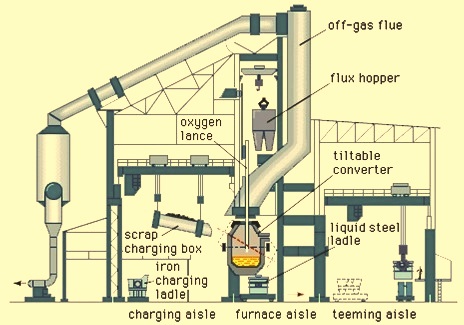
Fig 1 Typical schematic cross section of a converter shop
Before the beginning of a heat in the converter the HM is weighed out, sampled for chemical analysis and for temperature. This data, together with grade specifications, is used to calculate the amount of scrap, fluxes and O2 required. These amounts also depend on the levels of Si, and C etc., and temperature of the HM, since the heat generated by oxidation of the impurities must balance the requirements of bringing the scrap, fluxes and hot metal to the required temperature. In modern steel melting shops, a computer charge models determine the optimum proportions of scrap and HM, flux additions, lance height and oxygen blowing time, once the HM temperature and chemical analysis is known.
A heat begins when the converter is tilted about 45 degrees towards the charging bay and the pre weighed scrap charge is charged into the mouth of the converter from a scrap charging box with the help of the scrap charging crane. The HM is immediately poured directly onto the scrap from a transfer ladle by a HM charging crane. Fumes and kish (graphite flakes from the C saturated hot metal) are emitted from the converter mouth and collected by the pollution control system. Charging takes normally 2-3 minutes. After charging the converter is rotated to the vertical position, the lance is lowered to around 2.5 m to 3.0 m above the bottom of the converter. Through this lance, O2 is blown into the charge mix. The lance blows O2 on to the charge mix at high velocity and reactions commence. Seconds later ignition occurs when the CO from the reaction burns to carbon dioxide (CO2), producing a brilliant, luminous flame at the mouth of the converter. The amount of O2 used is around 55 -60 cum per ton of crude steel produced. The height of the lance above the liquid metal has an important effect on blowing characteristics and on the analysis of the steel. The operation starts with the lance in a high blow position which is around 3 m above the metal level in the converter. After a few minutes, after the flux is added and sufficient slag has formed, the lance is lowered to the low blow position.
After ignition, weighed amount of calcined lime/dolomite fluxes are dropped in the converter from overhead bins. Sometimes fluorspar is also dropped into the converter. These are the fluxes that form the slag. It is necessary early in the blow to form a fluid slag, which has the function of preventing sparking, the ejection of metal from the converter due to the impact of the O2 jet. To promote quick formation of slag, calcined lime is used. If raw limestone was used, its calcination would absorb heat from the process. Fluorspar is added to promote the fluidity of the slag. Any iron ore required (to adjust temperature) is then added with the remainder of the flux charge, whilst blowing continues. The complex flux charge is added within the first few minutes of the blow.
As blowing begins, an ear piercing shriek is heard. This is soon muffled as silicon from the HM is oxidized forming silica (SiO2), which reacts with the basic fluxes to form a gassy molten slag that envelops the lance. The gas is primarily CO from the C in the HM. The rate of gas evolution is many times the volume of the converter and it is common to see slag slopping over the lip of the converter, especially if the slag is too viscous. Blowing continues for a predetermined time based on the metallic charge chemistry and the liquid steel specification. This is typically 15 to 20 minutes, and the lance is generally pre-programmed to move to different heights during the blowing period. The lance is then raised so that the converter can be turned down towards the charging bay for sampling and taking of the temperature. Static charge models however do not ensure consistent turndown at the specified C and temperature because the HM analysis and metallic charge weights are not known precisely. Furthermore, below 0.2 % C, the highly exothermic oxidation of Fe takes place to a variable degree along with decarburization. The drop in the flame at the mouth of the converter signals low C, but temperature at turndown can be off by plus/minus 30 deg C to 50 deg C.
A steel sample is sent by pneumatic tube to the steel testing laboratory. Also temperature of the liquid steel is measured with the help of disposable thermo couples. On the basis of the temperature and the analysis, it is decided whether further adjustment is necessary. Coolant may be added to lower the temperature to the required tapping temperature, or there may be a short re-blow of oxygen to correct the analysis or increase the temperature, or both. When the tests and temperature readings are satisfactory the converter is tilted to the tapping position. Limestone, scrap, iron ore, sinter, and direct reduced iron are all potential coolants that can be added to a heat which has been overblown and is excessively hot. The economics and handling facilities dictate the selection at each shop.
Earlier, reblows or addition of coolants has resulted into increase in the tap to tap time. But these days, with more operating experience, better computer models, more attention to metallic input quality, and the availability of ladle furnaces for the adjustment of temperature, turndown control is more consistent. In some steel melting shops, sub-lance provides a temperature and C check about two minutes before the scheduled end of the blow. This information permits an in course correction during the final two minutes and better turn down performance. Sub-lance permits computer attainment of the end point and a significant reduction in the time between end of blow and tapping. However, operation of sub-lance is costly, and the needed information may not be always available due to malfunctioning of the sensors.
Once the heat is ready for tapping and the preheated steel teeming ladle (STL) is positioned in the ladle car under the furnace, the converter is tilted towards the tapping bay, and liquid steel pours through the tap hole from under the floating slag, into the STL below. The tap hole is located on one side in the upper cone section of the converter. Normally slag stoppers are used to prevent slag entering the STL as the converter is turned down. There are several types of slag stoppers (also known as slag darts) which are available. Slag stoppers normally work in conjunction with visual observation of the operator, which remain the dominant control device. Slag in the ladle results in P reversion, retarded desulphurization, and possibly steel with reduced cleanliness. Ladle additives are available to reduce the iron oxide (FeO) level in the slag but nothing can be done to alter the phosphorus.
After tapping steel into the STL, and the converter is rotated upside down for the tapping of the remaining slag into the slag pot. Then the converter is returned to the upright position. For some of the heats, the residual slag is blown with N2 to coat the barrel and trunnion areas of the vessel. This process is known as slag splashing (refer link article http://www.ispatguru.com/slag-splashing-technique-in-converter-operation/) . Near the end of a campaign, gunning with refractory materials in high wear areas may also be necessary. Once converter maintenance is complete the converter is ready to receive the charge for the next heat.
In case of combined blowing an inert gas is injected through porous plugs or tuyeres in the bottom of the converter. Bottom injection promotes mixing and gives improved yield due to decreased slopping. (Slopping occurs when a slag and steel are expelled from the converter during O2 blowing). (refer link article http://www.ispatguru.com/combined-blowing-process-in-converter-steel-making/ ).
The BOF process uses no additional fuel. The oxidation of HM impurities (C, Si, Mn, and P) supplies the heat. Oxidation of the molten metal and the formation of the slag is complicated process proceeding in several stages and occurring simultaneously on the boundaries between different phases (gas-metal, gas-slag, slag-metal). The chemistry of steel making in BOF is given in a separate article. ( refer link article http://www.ispatguru.com/chemistry-of-steelmaking-by-basic-oxygen-furnace/)
Most oxides are absorbed by the slag. Gaseous products CO and CO2 are transferred to the atmosphere and removed by the exhaust system. Oxidizing potential of the atmosphere is characterized by the post-combustion ratio, which is defined as CO2/(CO2+CO).
BOF process has limiting ability for desulphurization since the slag formed in the BOF is oxidizing (not reducing) therefore maximum value of distribution coefficient of sulphur in the process is about 10, which may be achieved in the slags containing high concentrations of calcium oxide (CaO).
In BOF steelmaking a high CaO/SiO2 ratio(normally 3 and above) in the slag is desirable. A rule of thumb is lime addition is to be 6 times the weight of Si charged. The MgO addition is dependent on the final tapping temperature and is normally designed to be around 8 % to 10% of the final slag weight at a tapping temperature of around 1650 deg C. This saturates the slag with MgO, thus reducing chemical erosion of the MgO based converter lining. (refer link article http://www.ispatguru.com/89/ )
Ferro alloys are charged from overhead bins into the STL. The common alloys are ferro-manganese, silico-manganese, and ferro-silicon.
Basic refractory linings are used for the lining of the converters. Magnesia – carbon refractory lining is the most used refractory lining for the converters. (refer link article http://www.ispatguru.com/refractory-lining-of-a-basic-oxygen-furnace/)
Environmental issues
The BOF process develops a dense brown fume of iron oxide in the waste gas. Environmental issue at BOF shops include the following.
- Capture and removal of contaminants in the hot and dirty primary off-gas from the converter
- Secondary emissions associated with charging and tapping the converter
- Control of emissions from ancillary operations such as HM transfer, and desulphurization etc.
- Recycling and/or disposal of collected oxide dusts or sludges
- Disposition of converter slag and converter muck.
Most BOF primary gas handling systems are designed on the principle of suppressed combustion systems where gases are handled in an uncombusted state and cleaned in electrostatic precipitators or wet gas scrubbing systems to clean the gasses from the dusts which is then collected as solids or slurry while the clean gas passes to the atmosphere through a stack or collected in a gas holder. The gas has a fairly good calorific value (1700- 2000 kcal/cum) and is used as a fuel in the steel plant. Suppressed combustion systems offer the potential for recovery of energy. (refer link article http://www.ispatguru.com/basic-oxygen-furnace-gas-recovery-and-cleaning-system/).
Secondary fugitive emissions associated with charging and tapping the BOF converter, or emissions escaping the main hood during oxygen blowing, may be captured by exhaust systems serving local hoods or high canopy hoods located in the trusses of the shop or both. Typically a fabric collector, or bag house, is used for the collection of these fugitive emissions. Similarly, ancillary operations such as HM transfer stations, and desulphurization etc. are usually served by local hood systems exhausted to fabric filters.
The particulate matter captured in the primary system, whether in the form of sludge from wet scrubbers or dry dust from precipitators, must be processed before recycling. Sludge from wet scrubbers requires an extra drying step. BOF dust or sludge is not a listed hazardous waste. It can be recycled to the blast furnace or sinter plant after briquetting or pelletizing.
BOF slags are often recycled through the sinter plant and blast furnace because of its high lime content. BOF slags are also used as rail road ballast.

Leave a Comment