Understanding Sinter and Sinter Plant Operations
Understanding Sinter and Sinter Plant Operations
Sintering is a process of agglomeration of fine mineral particles into a porous and lumpy mass by incipient fusion caused by heat produced by combustion of solid fuel within the mass itself. The sintering process is a pre-treatment step in the production of iron, where fine particles of iron ores and also secondary iron oxide wastes (collected dusts, mill scale etc.) along with fluxes (lime, limestone and dolomite) are agglomerated by combustion. Agglomeration of the fines is necessary to enable the passage of hot gases during the blast furnace operation.
Sintering has been referred to as the art of burning a fuel mixed with ore under controlled conditions. It involves the heating of fine iron ore with flux and coke fines or coal to produce a semi-molten mass that solidifies into porous pieces of sinter with the size and strength characteristics necessary for feeding into the blast furnace.
Although simple in principle, sintering plant requires that a number of important factors in its design and operation be observed to attain optimum performance. A simplified schematic flow diagram of sintering process is at Fig 1.
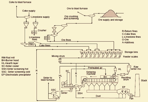
Fig 1 Simplified flow diagram of a sintering process
There are basically the following three types of sinters.
- Non flux or acid sinters – In these sinters no flux is added to the iron ore in preparing the sinter mix. Non flux sinters are very rarely being produced these days.
- Self fluxing or basic sinters – These are the sinters where sufficient flux is added in the sinter mix for producing slags of desired basicity (CaO/SiO2) in blast furnace taking into account the acidic oxides in the blast furnace burden.
- Super flux sinters – These are the sinters where sufficient flux is added in the sinter mix for producing slags of desired basicity in blast furnace taking also into account the acidic oxides in the coke ash in addition to the other acidic oxides in the blast furnace burden.
Fluxed sinters have superior high temperature properties in the blast furnace as compared to lump ore and acid sinters. These improvements include higher softening and melting temperatures and higher levels of reducibility.
The flexibility of the sintering process permits conversion of a variety of materials, including natural fine iron ores, ore fines from screening operations, captured dusts, ore concentrates, return fines not suitable for downstream processing, other iron-bearing materials of small particle size (sludges, mill scale etc.), and wastes and screenings of lime, limestone and dolomite into a clinker like agglomerate that is well suited for use in the blast furnace.
A sintering plant has become a tremendous success for providing a phenomenal increase in the productivity and saving in coke rate in the blast furnace. Fluxed sinter represents an improved blast furnace material as compared to sized iron ore. Improvements have been obtained by incorporating the blast furnace flux into the sinter rather than charging it separately at the top of the furnace, as it is needed to be done with the charging of only the sized iron ore. As per thumb rule, the use of fluxed sinter indicate that for each 100 kg of limestone per net ton of hot metal removed from the blast furnace burden and charged into the sinter plant to make a fluxed sinter, approximately 20-35 kg of metallurgical coke per ton of hot metal is saved and around 3 % to 5 % improvement in the productivity of blast furnace is achieved. The coke savings results primarily from calcining of limestone on the sintering grate rather than in the blast furnace.
Quality of sinters
Two important properties of sinter are basicity, which is controlled by the amount of limestone/lime, and strength, which is controlled by coke content.
The blast furnace demands sinter with a high cold strength, low reduction degradation index (RDI) and high reducibility index (RI) , in a very narrow band of chemistry variation, with the lowest possible fines content, and a good average size. The chemical and structural composition are very important in sinter, and it is good for the sinter to be stable so that both primary and final slags possess adequate characteristics in terms of softening and melting temperatures, liquid temperature and viscosity for the stable operation of the blast furnace.
It is important to have a high iron content, low gangue content, and basicity of the order of 1.6-2.1. Sinter reducibility, and sinter quality in general, improves with a higher level of hematite than magnetite, and its structure improves with a higher level of primary or residual hematite and ferrites than secondary or precipitated hematite.
The FeO content is an important control parameter in the sinter plant. When the chemical composition of an ore mix is fixed, FeO can provide an indication of sintering conditions, in particular the coke rate. A 2 % increase in the FeO content in sinter has been found to lower (improve) the RDI by 8 points. However, a higher FeO content negatively affects reducibility. It is important to find an optimum FeO content in order to improve the RDI without altering other sinter properties.
The alumina content has the most harmful effect. It deteriorates the sinter RDI, which increases as the alumina content rises. The strength and quality of sinter deteriorate as the alumina content rises. Alumina promotes the formation of silico ferrite of calcium and aluminum (SFCA). Alumina increases the viscosity of the primary melt that forms during the sintering process, leading to a weaker sinter structure with more interconnected irregular pores.
Sinter reducibility is determined by the chemical and mineralogical composition and by the pore structure.
MgO provides for an optimum blast furnace slag condition in terms of both good flowability and desulphurization. The addition of MgO to the raw mix improves the RDI.
It has been determined that replacing CaO with MgO in the form of dolomite for basicities of 1.6-1.9 leads to a slight reduction in sinter strength, reducibility and productivity. CaO combines with the iron oxides to form compounds with a low melting point that favour the formation of the primary melt, a minimum level of which is needed in order to manufacture a strong sinter. These compounds are Fe2O3·CaO (1205 deg C) and FeO·CaO (1120 deg C).
Silica (SiO2) combines with FeO and CaO to form compounds with a low melting point that favour the formation of the primary melt. These compounds are FeO·SiO2 (1180 deg C), 2FeO·SiO2 (1205 deg C), and FeO·SiO2·CaO (1223 deg C). Increasing the silica content and the basicity of the adherent fines causes the primary melt formation temperature to drop, which is favourable for the subsequent assimilation reaction at the liquid-solid interface between the fines and the nucleus particles.
After being tipped from the grates in the sintering machine, the sinter cake is crushed and hot screened. Its granulometric distribution is an important process parameter for sinter quality. The 10-30 mm fraction is sent directly to the blast furnace storage bins, the larger fraction is crushed to obtain smaller sized fractions, and the minus 5 mm fraction (return fines) is recycled to the sinter plant hoppers. For the good operation of the process, it is important to keep a balance between the generation and recycling of return fines.
Reducibility is an important characteristic of sinters which measures the ability to transfer oxygen during reduction in the blast furnace, giving an idea of fuel consumption needs in the furnace. The porosity and structure of the sinters and their mineral phases are intimately related with their reducibility. A heterogeneous structure is more reducible than a homogeneous structure.
The degradation of sinter is determined by the low temperature degradation index (LTDI) and the RDI. Degradation is originated, to a certain extent, in the transformation that takes place during the reduction of hematite to magnetite, accompanied by an increase in volume, giving rise to the presence of structural stresses in the sinter. The degradation of sinter in the blast furnace occurs during reduction in the low temperature zone, and has a harmful effect on the burden strength in the furnace, with the consequent loss of permeability to reducing gases and an increase in coke consumption. Low values of sinter degradation during reduction at low temperature are desirable.
The RDI is a very important parameter that is used as a reference in all sintering work and serves to predict the sinter’s degradation behaviour in the lower part of the blast furnace stack. A strong relationship exists between the RDI and the outdoor ambient temperature at the sinter plant. The RDI is also strongly dependent on the Ti content in the sinter, even when this is very small. There is no relationship with alumina but the coke ratio in the sinter mix is the most important control variable with regard to the RDI.
The cold strength of sinter is determined by the tumbler index, and depends on the strength of each individual ore component, the strength of the bonding matrix components and the ore composition. This index determines the size reduction due to impact and abrasion of the sinters during their handling, transportation, and in the blast furnace process. Cold mechanical strength is directly related with the tendency for fines to form during transportation and handling between the sinter machine and the blast furnace throat.
Sinter porosity is an important parameter that significantly affects its properties, in particular its reduction behaviour. It is seen that the pore diameter needs to be larger than 0.01 micrometer for the reducing gas to have sufficient access to the pores to satisfactorily reduce the sinter. When the micro pores are coalesced to pores of a size of more than 1 to 5 micrometer, the specific surface area of the sinter is decreased and so does its reduction. Elimination of the coalescence of micro pores and increase of the number of small pores make it possible to increase the surface area of the sinter and obtain a substantial improvement in its reducibility. Ferrites stabilize the micro pores and lead to a rise in porosity, thus achieving higher reducibility.
Given the diversity of the mineralogical components that comprise the sinter mix, as well as the heterogeneity of the mix, it is understandable that the sinter structure is complex and is being formed mainly by grains of iron oxide and calcium ferrites bonded by a gangue matrix. The ferrites, whose amount increases with the sinter basicity, are easily reduced, and by increasing the mechanical toughness of sinter to certain levels are considered very useful components. The ferrites are SFCA type and are formed by a solid-liquid reaction between hematite and the Fe2O3·CaO melt, with the subsequent assimilation of SiO2 and Al2O3 in the melt. The gangue is composed of calcium, iron and magnesium silicates that are difficult to reduce, and come to form part of the slag in the blast furnace.
Sintering plant operations
A typical sinter plant consists of a number of sequential operating units with the sinter machine at the heart of the plant.
Producing target quality of sinter needs accurate charging of the raw materials (ores, coke, additives, etc.). To modify the raw mix recipe, the coke addition, sinter basicity, raw material analyses and their influence on sinter parameters are to be taken into consideration. This procedure is complex. The purpose of the raw mix calculation is to establish a raw mix composition, in order to automatically achieve the assigned target values for coke addition, sinter basicity, total Fe, SiO2 balance, alumina balance and MgO balance.
The sintering process starts with the preparation of the raw mix. Materials consisting of ore fines, fluxes, in-plant waste material, fuel and return fines are stored in storage bins . They are mixed in the correct proportions using weigh hoppers/disc feeders, one per storage bin. For the return fines sometimes an impact meter is used instead. Weighing is continuous, as is the whole sintering process. The weighed materials pass along a conveyor to the primary mixing drum where water is added either manually or as a calculated percentage of the weight of material entering the mixing drum.
Coke breeze is need to be crushed (normally in four roll crusher) to obtain the correct particle size (0.25 mm to minus 3 mm) for enhancing sinter productivity and reducibility. Less than 0.25 mm coke size has a negative effect on the productivity, while size fractions of – 3.15 mm to + 1.00 mm shows better yields.
Fluxes namely limestone and dolomite are crushed (normally in hammer crushers) to obtain a minimum of 90 % of – 3 mm fraction.
Intimate mixing of the feed materials is one of the most important. A pre mix (usually called base mix) of the sintering ores, steel plant waste oxides, fluxes, and solid fuels is made in a revolving primary mixing drum is transferred to an open base mix blending yard. The blended base mix is then supplemented by small trim amounts of flux and solid fuel. This total feed mixture is the subject to a water addition within a mixing device such as a balling drum or disc. These mixers are operated to produce small size nodules or pellets which significantly improve the permeability of the sinter bed. balling drum is also called secondary mixing and nodulizing drum.
The amount of primary water added is proportional to the weight of base mix entering the balling drum. Water additions in the balling mixers are now automatically controlled these days .The secondary water feed set point is frequently taken as a proportion of the base mix belt weigher.
The continuous sintering process is carried out on a traveling grate of sinter machine that conveys a bed of prepared mix (sinter mix). The sinter mix is carefully conveyed to the sintering machine to ensure that permeability is maintained. In transferring the sinter mix from the balling mixer to the grate of the sintering machine, it is essential to feed the material carefully so as to provide a uniform, homogeneous bed and to prevent compacting of the bed. To avoid a direct drop of feed onto the grate, a hearth layer of about 25 mm to 50 mm of coarse (already sintered) material is fed first onto the traveling grate. Feeding devices typically include a roll feeder in conjunction with chutes which act to avoid compacting the sinter mix. Design of feed hoppers and feeders for distributing the prepared sinter mix into these hoppers is equally important since, if the sinter mix is compacted or segregated during handling and loading onto the grate (pellet), all of the advantages gained through good feed preparation may be lost. After this the sinter mix is leveled.
The bed depth is set and kept constant by adjusting the cut-off plate which is fitted with probes to sense the depth of material and automatically vary the roll feeder speed. The quantity of material in the feed hopper itself is held constant by automatic adjustment of the feed rates from the individual sinter mix bins.
Once the sinter mix is charged onto the travelling grate, metal bars or rods already inserted longitudinally along the grate for a distance of about 2 m to 4 m help to loosen up the mixture to enhance permeability.
Thereafter the surface of the sinter mix is ignited near the head or feed end of the travelling grate using a mixed gas (coke oven gas and blast furnace gas), or only coke oven gas or only blast furnace gas. In case of only blast furnace gas, it is usually preheated. Proper ignition of the sinter mix is important. Poor ignition results in spotty burning and may leave unsintered material over the surface of the bed. Conversely, too intense an ignition flame can result in slagging over the bed and reduced sintering rates. The radiant hood ignition furnace provides good ignition. The calorific value of the gas mixture and the set hood temperature are controlled. A separate control system is provided to maintain a fixed hood pressure by adjusting the wind box dampers immediately under the ignition hood.
As the sinter mix moves along on the traveling grate, air is sucked down by a draught fan through the ignited sinter mix layer to burn the fuel by downdraft combustion. As the grates move continuously over the wind boxes toward the discharge end of the strand, the combustion front in the bed moves progressively downward. This creates sufficient heat and temperature, about 1300 deg C to 1480 deg C, to sinter the fine ore particles together into porous clinkers. Gas circuit is to be fully leak proof, not allowing false air to be sucked by the system. This saves power in the waste gas circuit.
An important part of the sintering process is burn-through. The location along the traveling grate where the combustion front touches the bottom of the bed is called the burn through point. Burn-through point should ideally occur near the end of the strand bed. It is controlled by altering the strand speed. A number of variables affect the burn-through point, such as strand bed depth, water content and the quality of the sinter. Burn through is normally detected by temperature probes under the sinter bed. Burn through should be achieved but must not occur too soon after the ignition hood. The draught on the strand is maintained at a preset value by controlling the main fan louvers from pressure measurements in the wind main. This governs the point at which burn through occurs.
The strand speed is either controlled manually, or by measuring the waste gas temperatures as an indication of the burn-through point. If it occurs too early, the average waste gas temperature rises. If it occurs too late, the waste gas temperature decreases and the strand speed is slowed to compensate. Wind box temperatures can be used to improve the monitoring.
The suction produced by the main fan is varied by louvers near the fan inlet, which are controlled by a fan suction controller. If the waste gas temperature increases above a safe working limit a selector switch allows the waste gas over temperature controller to position the louvers.
Depending upon the characteristics of the ore materials and the sintering conditions, daily average production rate of 22.5–44 tons/sq m/day of grate area is expected from the sinter machines.
After the end of the travelling grate, the sinter passes through a spiked roll crusher and the hot screens to the sinter cooler. A number of fans are usually used for cooling, and the speed of the cooler is to match the demand of the travelling grate and is determined by the travelling grate speed and the bed depth. The fines removed by the hot screens are conveyed to the return fines bin.
Cooling of the sinter below 150 deg C, so that it can be handled on conveyor belts, is an important part of the operation. Sinter coolers can be either rotary coolers or straight line coolers. Rotary coolers are more commonly used. It is desirable to avoid a water quench as the quench adversely affects sinter properties. The exhaust air from these coolers is used for recovery of heat in some of the sinter plants.
After cooling, the sinter is passed into the discharge bunker. At this stage, the level is controlled by varying the outlet feed rate (usually vibro feeders). The sinter then passes to the cold screening area, where it is passed through crushers and screens for the separation of product sinter, bedding and return fines. Return fines, not suitable for downstream processing, are conveyed to a bin for recycling in the sintering process.
Use of sized sinter is desirable for the improvement of production rates in the blast furnace. Further, crushing the sinter to 30 mm size at the sinter plant yields a more stable sinter because the smaller size fractions are more resistant to degradation.
A supervisory station controls all steps of the sintering process. From the control room the operator has full control of the entire plant through the PC terminals.
Other articles on sinters and sintering process are available under following links
http://www.ispatguru.com/the-sintering-process-of-iron-ore-fines-2/
http://www.ispatguru.com/technologies-for-improvement-in-sintering–
http://www.ispatguru.com/sinter-quality-and-process-of-sintering-iron-ores/
http://www.ispatguru.com/iron-ore-sinter/

Leave a Comment