Steel and Transmission of Electric Power
Steel and Transmission of Electric Power
Transmission of electric power is a process by which the electric power produced at power plants is transported in bulk quantities over long distances for eventual use by consumers. The ultimate objective of electric power transmission is to provide power to customers economically, safely, reliably, efficiently, and with minimal environmental impact. Each of these aspects has one or more quantitative measure, such as price per kilowatt-hour, number and lethality of accidents, frequency and duration of service interruptions, generating plant heat rate, transmission and distribution losses, and emissions factors. Transmission systems are designed, and their individual components selected, with all of these objectives in mind, though they may be optimized differently in different systems.
Power transmission process has got three main components (Fig 1). They are (i) substations, (ii) transmission poles and towers, and (iii) electricity conductors. Steel plays a major role in all these three components of transmitting power from the point of generation to the consumers.
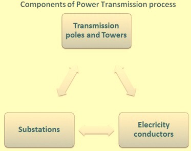
Fig 1 Components of power transmission process
Steel use in substations
Substations transform voltage from high to low, or the reverse, or perform any of several other important functions. Substation varies in size and configuration. Between the generating station and consuming point, electric power may flow through several substations at different voltage levels. A substation consists of (i) outdoor switch yard, (ii) a building which houses the control equipment, and (iii) the fencing.
The outdoor switch yard has (i) structures at dead-end, (ii) static poles, and bus supports and equipment stands. It has also got the grounding arrangement.
Structures at dead-end are those structures where the transmission line ends or angles off. They are typically constructed with heavier structural steels in case they are needed to carry heavier tension. The two most common dead-end structures are A-frame and H-frame structures. The structures at the dead end are to be designed to the conductor, wind, and ice (in case of cold climates) loading conditions and required strength requirements.
Static pole is a usually single free-standing steel pole that creates a shield to protect all of the equipment inside a substation from lightning. Static poles may or may not have overhead shield wires attached to enhance protection.
Main equipments needed in the outdoor switch yard are main transformer, potential transformer, current transformer, coupling capacitor voltage transformers, lightening arrestors, and different types of switches. While the main transformer is erected on an RCC (reinforced cement concrete) foundation, rest of the equipments are erected on steel stands, fabricated with structural steels of shapes beams, channels and angles etc. For RCC foundations reinforcement steel bars are used of the required size and strength. Some of the switch yard equipments have significant weight and the steel structural stands are to be designed not only to take care of these weights but also other structural loads due to the deflection limits and clearance requirements. Structures are to be designed to resist all applied loads including, but not limited to, conductor tension, wind, ice ( in case of gold climate), and short circuit forces. In addition to strength requirements, structures are to be proportioned such that the load-induced deflections do not hinder the functionality of the structure and the equipment it supports.
The core of the transformers is made of electrical steel, also called lamination steel, silicon electrical steel, silicon steel, relay steel or transformer steel. This steel is specialty steel tailored to produce certain magnetic properties, such as a small hysteresis area (small energy dissipation per cycle, or low core loss) and high permeability. The material is usually manufactured in the form of cold rolled strips less than 2 mm thick. These strips are called laminations when stacked together to form a core. Once assembled, they form the laminated core of the transformer.
Platforms for the operation and the maintenance of the equipments in the switch yard are made of steel and it need to be properly grounded with the yard grounding system.
Bus supports are the most basic structure made of steel found inside a substation. Its main purpose is to provide support for rigid bus as it travels though the substation.
All the steel structures in the outdoor switch yard are normally galvanized to protect them from corrosion. Heavy galvanized coating is applied in the coastal and industrial areas where corrosion rates are normally high. Weathering steel can also be used for these structures.
The building housing control equipment is usually made of reinforced cement concrete. The control building needs steel reinforcement bars during its construction. Electric cables in the control room are erected on cable racks made of steel.
The fencing of the substation is normally made from galvanized steel. The fencing generally consists of two meters of steel fabric with three strands of barbed wire on a single bayonet which extends out of the substation at a 45 deg angle above the fabric. The vertical height of bayonets is normally around 300 mm resulting in a total fence height of around 2.3 meters.
The metallic steel fencing of the substation is to be considered just as other substation structures. The reason for this is that the overhead high voltage (HV) lines entering or leaving a substation may snap and fall on the fence. Unless the fence is integrated with the rest of the substation grounding system, a dangerous situation may develop. Persons or livestock in contact with the fence may receive dangerous electric shocks.
Steels for transmission poles and towers
The transmission towers support the conductors and provide physical and electrical isolation for the energized lines. The minimum set of specifications for towers are the material of construction, type or geometry, span between towers, weight, number of circuits, and circuit configuration. At high voltage, the material of construction is generally steel. The type of tower refers to basic tower geometry. The options are lattice, pole (or monopole), H-frame, guyed-V, or guyed-Y. The span is commonly expressed in the average number of towers per kilometer. The weight of the tower varies substantially with height, duty (straight run or corner, river crossing, etc.), material, number of circuits, and geometry. The type of tower (specific tower geometry) is very site-dependent, and, for any given conditions, multiple options are likely to exist.
The basic function of the tower is to isolate conductors from their surroundings, including other conductors and the tower structure. Clearances are specified for phase-to-tower, phase-to ground, and phase-to-phase. These distances are maintained by insulator strings and must take into account possible swaying of the conductors. The clearance is maintained by setting the tower height, controlling the line temperature to limit sag, and controlling vegetation and structures in the ROW (right of way).
Besides electricity conductors main components of an overhead power transmission line consist of supporting structures, insulators, cross arms, and miscellaneous items such as phase plates, danger plates, lightning arrestors, and anti-climbing wires etc.
Supporting structures are either poles or towers which keeps the conductors at suitable level above the ground. The property requirements for these supporting structures are as follows.
- High mechanical strength to withstand the weight of equipment and wind loads etc.
- Light in weight without the loss of mechanical strength
- Have components which are easy to assemble
- Cheap in cost and economical to maintain
- Longer life
- Easy accessibility of electricity conductors for maintenance
The supporting structures used for transmission of electricity are normally poles or lattice towers. Poles are used for low voltage transmission and for shorter distances and they can be made of wood, RCC, or steel. The lattice towers are made only of steel and used for long distance transmission at high voltage..
The RCC poles use steel reinforcement for its manufacture. Steel poles possess gretater mechanical strength, have longer life, and permit longer spans. These poles are normally used in urban areas. Steel poles need to be galvanized or painted to increase their lives. The steels normally used for these poles are mild steel and the shapes used are rails, rolled joists, or tubular products.
Steel transmission towers are space steel structures made by the latticework of steel girders and diagonal braces. The individual pieces are made from rolled steel profiles and then bolted together at the site. Corrosion protection of all tower parts is made by hot dip galvanizing. Weathering steel is also used for corrosion protection.
Steel transmission towers have greater mechanical strength, longer life, and permit the use of longer spans. The risk of interrupted service due to broken or punctured insulation is considerably reduced owing to longer spans. Tower footings are usually grounded by driving steel rods into the earth. This minimizes the lightening troubles as each tower acts as a lightning conductor. Most steel transmission towers are designed to support one or two circuits, although some have been designed to support three or four circuits. Each circuit consists of three phases.
Steel transmission towers are normally of the following three general types:
- Tangent towers – They are used where the line is straight or have an angle not exceeding 30 deg. They support vertical loads, transverse and longitudinal wind loads, a transverse load from the angular pull of the wires, and a longitudinal load due to unequal spans, forces resulting from the wire-stringing operation, or a broken wire.
- Angle towers – They are used where the line changes direction by more than 30 deg. They support the same kinds of load as the tangent tower. The number of groups and the range of line angle in each group depend on the layout of the line.
- Dead-end towers – They are also called anchor or strain towers. They must take and dead-end pulls from all the wires on one side, in addition to the vertical and transverse loads.
Tangent towers are the most used towers and constitutes around 70 % to 80 % of all the towers in a long line. Three items are normally considered for the tower design. These are (i) cost of material, (ii) cost of erection, and (iii) cost of foundations. The cost of the material is directly related to the weight of the tower. The cost of erection is directly related to the number of pieces and number of bolts to be installed. The lightest tower may not be the most economical if it contains many more pieces per ton than a slightly heavier one, because more pieces must be handled in fabrication, shipment, storage, and erection. The cost of foundations is directly related to the spread of the tower legs. A tower with closely spaced lags will have shorter lacing members, but the higher stresses in the legs will increase foundation costs.
Poles made of tubular steel generally are assembled at the factory and placed on the right-of-way afterward. Because of its durability and ease of manufacturing and installation, many utilities in recent years prefer for low voltage application, the use of mono-polar steel or concrete towers over lattice steel for new power lines and tower replacements.
A lattice tower is a framework construction made of steel sections. Lattice towers are used for power lines of all voltages, and are the most common type for high-voltage transmission lines. Lattice towers are usually made of galvanized steel. A lattice tower is usually assembled at the location where it is to be erected. This makes very tall towers possible (up to 100 meters—in special cases even higher). Assembly of lattice steel towers can be done using a crane. Lattice steel towers are generally made of angle-profiled steel beams (L- or T- beams). For very tall towers, trusses are often used.
Towers may be self-supporting and capable of resisting all forces due to conductor loads, unbalanced conductors, wind and ice (in cold climates) in any direction. Such towers often have approximately square bases and usually four points of contact with the ground.
A semi-flexible tower is designed so that it can use overhead grounding wires to transfer mechanical load to adjacent structures, if a phase conductor breaks and the structure is subject to unbalanced loads. This type is useful at extra-high voltages, where phase conductors are bundled (two or more wires per phase). It is unlikely for all of them to break at once, barring a catastrophic crash or storm.
A guyed tower has a very small footprint and relies on guy wires in tension to support the structure and any unbalanced tension load from the conductors. A guyed tower can be made in a V shape, which saves weight and cost,
The amount of steel used in a transmission structure can be significantly reduced by the use of guy steel wires. These guy wires assist the structure to resist the horizontal forces due to the conductors. Since the guy wires create obstruction to any type of other work in the area, the use of guyed structures get limited to only those areas where guys do not affect the use of any other machinery.
Electricity conductor material
The electricity conductor is one of the important items in a transmission system since it constitutes the major investment. So the proper choice of material and size of conductor is of considerable importance. The conductor material used for power transmission and distribution needs to have the following characteristics.
- High electric conductivity
- High tensile strength in order to withstand mechanical stress
- Low cost so that it can be used for long distances
- Low specific gravity so that weight per unit volume is small
All the above requirements are not found in a single material. Hence a compromise is usually made between cost and the required electrical and mechanical properties while selecting a conductor material.
In early days conductors used on transmission and distribution lines were usually copper. But aluminum conductors have completely replaced copper because of much lower costs and lighter weight of aluminum as compared to copper, having similar resistance. Aluminum conductors are of different types such as (i) all aluminum conductor (AAC), (ii) all alloy aluminum conductor (AAAC), (iii) aluminum conductor steel reinforced (ACSR), and iv) all aluminum alloy conductor steel reinforced (AACSR). The major difference between AAC, AAAC, and ACSR conductors are the materials they are constructed from. AAC is manufactured from electrolytically refined aluminum with 99.55 % minimum purity. AAAC is made from an aluminum alloy. Due to low tensile strength, aluminum conductors produce greater sag. This prohibits their use for larger spans and makes them unsuitable for long distance transmission. In order to increase the tensile strength, the aluminum conductor is reinforced with a core of galvanized steel wires. The composite conductor thus obtained is known as aluminum conductor steel reinforced (ACSR). The most common conductor in use for transmission today is aluminum conductor steel reinforced.
ACSR consists of central core of galvanized steel wires surrounded by a number of aluminum strands. Normally, diameter of both steel and aluminum wire is the same. The cross-section of the two metals is usually in the ratio of 1:6 (Fig 1). In the composite conductor of ACSR, steel takes the greater percentage of mechanical strength while aluminum strands carry the bulk of the current. In these conductors galvanized steel is used to prevent rusting and electrolytic corrosion. ACSR conductors have the following advantages.
- The reinforcement with steel increases the tensile strength but at the same time keeps the composite structural lighter. The reinforcement with steel though increases the weight, but still ACSR conductor is having 25 % less weight than the weight of an equivalent copper conductor. Due to this reason, ACSR conductors produce less sag and hence longer spans can be used.
- Due to smaller sag in case of ACSR conductors, Tower of smaller heights can be used.
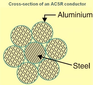
Fig 1 Cross-section of ACSR conductor
Galvanized steel conductors can be used for extremely long spans or for short line sections exposed to abnormally high stresses due to climatic conditions. This is feasible since steel has very high tensile strength. Galvanized steel conductors have been found very suitable in the rural areas where cheapness is the main consideration. Due to poor conductivity and high resistance of steel, such conductors are not suitable for transmitting large power over a long distance. However, they can be used to advantage for transmitting a small power over a small distance where the size of the copper conductor desirable from economic considerations is too small and thus unsuitable for use because of poor mechanical strength.

Leave a Comment