Recovery of Waste Heat
Recovery of Waste Heat
Waste heat is the heat which is generated in a process due to the combustion of fuel or due to a chemical reaction and then discharged into the environment without being put to practical use. Sources of waste heat include hot combustion gases discharged into the atmosphere, process off gases, conductive, convective and radiative losses from equipment and the heated products leaving various industrial processes (hot coke, hot metal, liquid steel, and hot rolled product etc.), and heat transfer from hot equipment surfaces (heat transferred to cooling water).
Waste heat recovery consists of the capture and reuse of the waste heat of the industrial processes for heating or for generating mechanical or electrical work. Typical uses include combustion air preheating, preheating of fuel gas, boiler feed water preheating, raw material preheating, generation of process steam, and production of steam for power generation etc. The basic idea behind the recovery of the waste heat is to try to recover maximum amounts of heat in the plant and to reuse it as much as possible, instead of just releasing it into the environment (air or a nearby river).
Waste heat is intrinsic to all manufacturing processes. During the industrial manufacturing processes, around 20 % to 50 % of the energy consumed is ultimately lost via waste heat contained in streams of hot exhaust gases and liquids, as well as through heat conduction, convection, and radiation from the surface of the hot equipments as well as from the heated products. Waste heat recovery is a valuable alternative approach for improving overall energy efficiency improvements of the industrial furnaces. Energy efficiency which can be achieved through waste heat recovery is normally in the range of 10 % to 50 %.
The essential fact is not the amount of heat, but rather its value. The mechanism to recover the unused heat depends on the temperature of the waste heat fluids and the economics involved. Waste heat recovery technologies frequently reduce the operating costs for facilities by increasing their energy productivity. Captured and reused waste heat is an emission free substitute for costly purchased fuels or electricity.
Fig 1 shows typical energy flow without and with heat recovery.
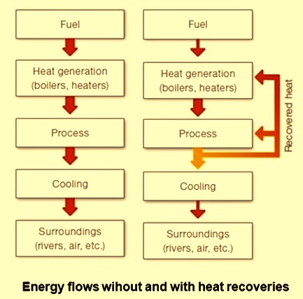
Fig 1 Typical energy flow without and with heat recovery
Three essential components which are necessary for waste heat recovery are namely (i) an accessible source of waste heat such as combustion exhausts, process exhausts, hot gases from the furnaces, cooling tower water etc. , (ii) a recovery technology such as regenerator, recuperator, economizer, waste heat boiler, thermoelectric generator etc. , and (iii) a use for the recovered energy such as preheating of boiler feed water, raw materials and combustion air preheating, generation of steam or/and electrical power, and preheating of low calorific value combustion gases like blast furnace gas etc..
Waste heat recovery equipment
There are several heat recovery equipments being used in a steel plant. Major among them are given below. Heat exchangers are most commonly used to transfer heat from combustion exhaust gases to combustion air entering the furnace. Since preheated combustion air enters the furnace at a higher temperature, less energy need be supplied by the fuel. Typical technologies used for air preheating are given below.
- Recuperators – Recuperators recover exhaust gas waste heat in medium to high temperature applications. Recuperators can be based on the principle of heat transfer by radiation, convection, or combinations. Recuperators are constructed out of either metallic or ceramic materials. Metallic recuperators are used in applications with temperatures below 1050 deg C, while heat recovery at higher temperatures is better suited to ceramic tube recuperators which can operate with hot side temperatures as high as 1500 deg C and cold side temperatures of about 950 deg C.
- Regenerators – Regenerators consist of two brick ‘checker work’ chambers through which hot and cold airflow alternately. As the combustion exhausts pass through one chamber, the bricks absorb heat from the combustion gas and there is increase in its temperature. After the bricks pick up heat, the flow is then changed so that the incoming combustion air passes through the hot checker work, which transfers heat to the combustion air entering the furnace. A minimum of two chambers are used so that while one is absorbing heat from the exhaust gases, the other is transferring heat to the combustion air. The direction of airflow is altered about a fixed interval of time. Regenerators are specially suited for high temperature applications with dirty exhausts. One major disadvantage is the large size and capital costs, which are significantly greater than costs of recuperators.
- Passive air preheaters – These are gas to gas heat recovery devices for low to medium temperature applications where cross contamination between gas streams are required to be prevented. Passive preheaters are usually of two types namely (i) the plate type and (ii) the heat pipe type. The plate type preheater consists of multiple parallel plates that create separate channels for hot and cold gas streams. Hot and cold flows alternate between the plates and allow significant areas for heat transfer. The heat pipe heat exchanger consists of several pipes with sealed ends. Each pipe contains a capillary wick structure that facilitates movement of the working fluid between the hot and cold ends of the pipe. Hot gases pass over one end of the heat pipe, causing the working fluid inside the pipe to evaporate. Pressure gradients along the pipe cause the hot vapour to move to the other end of the pipe, where the vapour condenses and transfers heat to the cold gas. The condensate then cycles back to the hot side of the pipe via capillary action.
- Recuperative or regenerative burners – Burners that incorporate recuperative or regenerative systems are simpler and more compact in design and construction than a standalone recuperators or regenerators. These systems provide increased energy efficiency compared to burners operating with ambient air. A self recuperative burner incorporates heat exchange surfaces as part of the burner body design in order to capture energy from the exiting flue gas, which passes back through the body. Self regenerative burners pass exhaust gases through the burner body into a refractory media case and operate in pairs similar in a manner to a regenerator. Typically, recuperative burner systems have less heat exchange area and regenerative burner systems lower mass than standalone units. Hence, their energy recovery is lower but their lower costs and ease of retrofitting make them an attractive alternative for energy recovery.
- Shell and tube heat exchangers – When the medium containing waste heat is a liquid or a vapour which heats another liquid, then the shell and tube heat exchanger is normally used since both paths must be sealed to contain the pressures of their respective fluids. The shell contains the tube bundle, and usually internal baffles, to direct the fluid in the shell over the tubes in multiple passes. The shell is inherently weaker than the tube, so that the higher pressure fluid is circulated in the tubes while the lower pressure fluid flows through the shell. When a vapour contains the waste heat, it usually condenses, giving up its latent heat to the liquid being heated. In this application, the vapour is almost invariably contained within the shell. If the reverse is attempted, the condensation of vapours within small diameter parallel tubes causes flow instabilities. Tube and shell heat exchangers are available in a wide range of standard sizes with many combinations of materials for the tubes and shells.
- Finned tube heat exchanger or economizer – Finned tube heat exchanger is used to recover heat from low to medium temperature exhaust gases for heating liquids. Applications include boiler feed water preheating and hot process liquids etc. The finned tube consists of a round tube with attached fins that maximize surface area and heat transfer rates. Liquid flows through the tubes and receives heat from hot gases flowing across the tubes. A finned tube exchanger where boiler exhaust gases are used for feed water preheating is generally referred to as a boiler economizer.
- Waste heat boiler – Waste heat boiler is a water tube boilers that uses medium to high temperature exhaust gases to generate steam. Waste heat boilers are available in a variety of capacities allowing for gas intakes ranging from 30 to 25000 Cum /min. In cases where the waste heat is not sufficient for producing desired levels of steam, auxiliary burners or an afterburner are usually added for obtaining higher output of steam. The steam can be produced for process purpose or for generation of power. Generation of superheated steam normally needs addition of an external superheater to the boiler.
- Load preheating – It refers to the use of waste heat leaving a system for preheating the load entering the system. The most common example is boiler feed water preheating, where an economizer transfers heat from hot combustion exhaust gases to the water entering the boiler. Other applications utilize direct heat transfer between combustion exhaust gases and solid materials entering the different furnaces.
- Heat pumps – Waste heat is sometimes available at a temperature lower than the potential load requirement. In such a case waste heat upgrading is needed. waste heat upgrading refers to boosting the energy level of a waste heat stream so that it might perform useful function that otherwise can be achieved. This is accomplished through the use of heat pumps or by direct vapour compression where the waste heat is available in the form of vapour. The majority of heat pumps work on the principle of the vapour compression cycle. In this cycle, the circulating substance is physically separated from the source (waste heat, with a temperature of Tin) and user (heat to be used in the process, Tout) streams, and is reused in a cyclical fashion, therefore called closed cycle heat pump.
The benefits of the waste heat can be broadly classified in two categories, namely (i) direct benefits, (ii) indirect benefits.
- Direct benefits are reflected by the reduction in the consumption of the resources and utilities and also the operating costs, since recovery of waste heat improves the energy productivity of the process and has a direct effect on the efficiency of the process. In the present scenario of global climate change, the biggest benefit of the waste heat recovery is that it is a green house gas free source of energy.
- The indirect benefits of the waste heat recovery are reduction in environmental pollution, reduction in the consumption of energy for auxiliary uses and reduction in the equipment sizes. Waste heat recovery reduces the fuel consumption, which leads to reduction in the flue gas produced. This results in reduction in equipment sizes of all fuel gas handling equipments such as fans, stacks, ducts, burners, etc. Reduction in equipment sizes gives additional benefits in the form of reduction in auxiliary energy consumption like electricity for fans, pumps etc.
The other aspects of the waste heat recovery system are that there is need of additional space, capital and operating cost which need to be justified from the benefits gained in terms of het recovered.
Waste heat recovery technologies, although currently employed to varying degrees at many places in steel plants, face technical and economic barriers that impede their wider applications. Though many of the technologies are already well developed for waste heat recovery (e.g. recuperators and regenerator etc.) yet there is the challenge that these technologies are not always economical for a given application (e.g. application with dirty exhaust streams).
There are many barriers which impact the economy and effectiveness of heat recovery equipment and impede their wider installation. Many of these barriers are interrelated, but can generally be categorized as related to cost, temperature restrictions, chemical composition, application specifics, and inaccessibility/transportability of heat sources.
Present practices being adopted for the waste heat recovery show that waste heat is normally recovered from clean, high temperature waste heat sources in large capacity systems. Hence there are opportunities available in optimizing existing systems, developing technologies for chemically corrosive systems, recovering heat from non fluid heat sources, and recovering low temperature waste heat.
While economics often limit the feasibility of low temperature waste heat recovery, there are various applications where low grade waste heat has been cost effectively recovered for use in industrial facilities. A large amount of industrial waste heat is available only in the low temperature range. As an example, combustion systems such as boilers frequently use recovery technologies that exhaust gases in the temperature range of 120 deg C to 150 deg C. Also, large quantities of waste heat can be found in industrial cooling water and cooling air. An integrated steel plant in Japan has installed a power generation plant with a 3.5 MW capacity using cooling water at only 98 deg C.
In the case of combustion exhaust gases, substantial heat can be recovered if water vapour contained in the gases is cooled to lower temperatures. Minimum temperature limits around 120 deg C to 150 deg C are frequently employed in order to prevent water in the exhaust gases from condensing and depositing corrosive substances on the heat exchanger surface. However, cooling the flue gas further could significantly increase heat recovery by allowing the latent heat of vaporization to be recovered. This latent heat comprises a significant portion of the energy contained in exhaust gases. Technologies that can minimize chemical attack while cooling exhaust gases below the condensation point can achieve significant increases in energy efficiency via recovering the latent heat of evaporation.
Presently low temperature heat recovery faces at least three challenges namely (i) corrosion of the heat exchanger surface, (ii) large heat exchange surfaces required for heat transfer, and (iii) finding a use for low temperature heat.
Technologies are available that can cool gases below dew point temperatures to recover low temperature waste heat. These technologies include deep economizers, indirect contact condensation recovery, direct contact condensation recovery, and recently developed transport membrane condensers. Commercialization of these technologies has been limited due to high costs and because facilities lack an end use for the recovered heat. When facilities lack an end use for waste heat, some have found other means for recovery, including heat pumps and low temperature power generation. Use of these technologies are also frequently limited by economic constraints.

Leave a Comment