Mini Blast Furnace and Iron making
Mini Blast Furnace and Iron making
Mini blast furnaces (MBF) are generally viewed as miniature versions of the conventional large blast furnaces (BF). These furnaces are ideally suited for small scale operations. In fact, they are basically the forerunner to modern conventional last blast furnaces and hence they have operated for a longer period of time. MBFs are located in many countries but the majority of the MBFs are located in China, India, Brazil and Indonesia. Plant availability as well as the perfection achieved in this technology has made MBF an accepted route for iron making. Further, these days, most of the technologies of design, burdening and operation which have become the norm for today’s modern large furnaces have also been adopted in MBFs.
MBF is a vertical shaft furnace with a crucible like hearth. Burden materials consisting of iron ore, coke or charcoal used as a reducing agent as well as fuel, and fluxes, usually limestone or dolomite, are charged into the top of the furnace. The furnace works on the principle of a counter current reactor. As the burden descends through the shaft, it is preheated and pre-reduced by the hot gases ascending from the furnace bottom. The gases are generated by introducing hot air blast enriched with oxygen through tuyeres. The hot blast burns the reducing agent, producing reducing gases and heat required for the reduction process taking place in the furnace. The reduced burden material melts to form HM (liquid iron) which becomes saturated with carbon and descends to the hearth. The fluxes combine with the impurities in the burden materials to produce a molten slag which accumulates on top of the liquid iron in the hearth. Liquid iron and liquid slag are periodically tapped from the furnace.
MBF exhibits flexibility and competitiveness and it is suitable for the production of both basic and foundry grade hot metal (HM). The important characteristic features of a MBF include both the simplicity and economy. Other features of MBF are as follows.
- Proven technology and equipment.
- Simpler design and equipment than conventional large BF.
- It has flexibility with ore burdening with ore burdens can vary from 100 % iron ore lumps to any blend of iron ore lumps and agglomerates (sinter or pellets) in the burden composition.
- A range of reducing agents can be used including low quality coke and charcoal.
- The quality of HM produced is similar to that of conventional large BF.
- Its operation and maintenance is similar but more flexible than conventional large BF.
- It has low capital cost as well as lower cost of equipment maintenance.
- It is an economic and reliable source of HM for iron foundries as well as in mini steel plants where it is used in forward integration with steelmaking shops consisting of induction furnace / electric arc furnace / energy optimizing furnace and sometimes even with small basic oxygen furnace.
As the name suggest, the size of MBF is small with the internal volumes ranging from 35 cum to 600 cum. MBFs are generally low shaft furnaces with the effective height of the furnaces varying from less than 12 m to around 20 m. MBFs achieves normally productivity levels which is in the range of 2 tins/cum/day to well above 3 tons/cum/day.
Important features of a MBF
MBF is a shaft type furnace with a vertical stack superimposed over a crucible like hearth. MBF complex is composed of BF proper, hot blast stoves, MBF top and charging system, Several maintenance platforms, stock house system with several bins for burden materials, tuyere platform and cast house, slag granulation system, gas system, BF gas cleaning system, raw material and fuel supply system, power supply and other utilities supply systems as well as air blower station and BF water circulating system etc. The layout of the MBF is usually very compact with most of the facilities which supports HM production, are installed very near to the furnace proper. A typical process flow sheet of a MBF with a dry gas cleaning plant is shown in Fig 1.
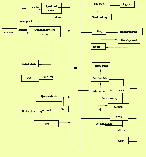
Fig 1 Typical process flow sheet of a MBF with a dry gas cleaning plant
The furnace which is the processing reactor, takes part in the iron production system in the following way.
- It receives the already prepared burden materials from the storages through the feeding system.
- It receives hot blast which has been generated by the air blower at the blowing station and heated in the hot blast stoves. The hot blast is normally enriched with oxygen.
- It produces and delivers HM and liquid slag.
- It delivers the raw BF gas to the gas cleaning system.
- It receives cooling water and compressed air through the cooling and utilities system.
- It is supplied with electric power by the electric system.
- It is controlled by means of the command and control system.
MBF has generally a self-standing frame structure with four columns supporting 6 platforms and skip-bridge (in case of skip charging) standing directly on the RCC foundation. The furnace shell is usually built of structural steel plate of different thicknesses.
The typical profiles of two Chinese MBFs are given at Tab 1.
| Tab 1 Typical profiles of Chinese mini blast furnaces | ||||
| Sl.No. | Parameter | Unit | Value | |
| 1 | Effective volume | cum | 50 | 320 |
| 2 | Hearth diameter | m | 2.25 | 4.9 |
| 3 | Belly diameter | m | 3.05 | 5.7 |
| 4 | Throat diameter | m | 2 | 3.7 |
| 5 | Height of dead layer | m | 0.35 | 0.6 |
| 6 | Height of hearth | m | 1.8 | 2.7 |
| 7 | Height of bosh | m | 2.3 | 2.9 |
| 8 | Height of belly | m | 1 | 1 |
| 9 | Height of shaft | m | 5.3 | 9.2 |
| 10 | Height of throat | m | 1.27 | 1.6 |
| 11 | Effective height | m | 12.02 | 17.4 |
| 12 | Stack angle | Deg | 84.27 | 83.79 |
| 13 | Bosh angle | Deg | 81.57 | 82.15 |
| 14 | Height/diameter ratio | 3.58 | 3.05 | |
| 15 | Number of tuyeres | Nos. | 6 | 12 |
In modern MBFs, semi-graphite carbon blocks are normally used for BF bottom and the cast carbon blocks for hearth. Carbon blocks with good heat conductivity and erosion resistance can effectively protect BF bottom and hearth. Ceramic cup structure is generally used for hearth inner wall with alumina lining. Corundum bricks and alumina bricks are used in the taphole area and slag notch area respectively. The bosh, belly and partially stack area is lined normally with alumina bricks. High density fireclay bricks are used in the upper stack area for the lining. Furnace inner shell is usually sprayed with alumina castables to have a thickness of 70 mm. For the BF throat and top cover inner lining, welding of anchors and one layer of heat-resistant and wear resistant castables are used. Depending on the furnace lining design, the expected campaign life of MBF varies in the range between 5 years to more than 10 years.
Increase of the hot blast temperature is one of the major measures for increasing the volume of pulverized coal injection in the MBF and reducing the coke rate in the MBF. The hot blast system design is done normally in such a way so that the hot blast temperature can be maintained at 1200 deg C by using the BF gas as fuel. These days, MBFs are equipped with 3 numbers hot blast stoves with rotary tangential dome combustion design.
The tuyeres are fed with hot blast from the bustle main through blow pipes. The tuyeres are installed along with tuyere coolers. Both are made of copper. The number of tuyeres installed in the MBF depends on the useful volume of the MBF and are designed for optimum blast velocity which is normally in the range of 210 m/second to 230 m/second under operating conditions.
These days modern MBFs have one taphole from where both hot metal and slag flows. They are separated by a skimmer plate, properly located in the HM runner placed on the working platform. In some MBFs there are separate slag notch for tapping of liquid slag. Hot metal flows into the ladle or torpedo car, while liquid slag is conveyed to a slag granulation system.
Cooling staves are being used in MBFs with 3 sections of plain-surface staves used in bottom and hearth and staves with refractory inserted into them used in bosh and belly zones. Step-staves are being used for stack area in order to effectively support the brick lining of lower stack and to reduce the opening of BF shell to for increasing the MBF tightness. Staves of ferrite nodular cast iron are generally used for middle and lower stack. Seamless steel tube is casted inside the stave and rib plate on the hot surface of the stave. Carbon material is rammed in the groove. Water cooling is normally used for MBF bottom. The tuyere system is cooled by a dedicated water cooling system.
Other auxiliary equipment for blast furnace proper are (i) 2 stage throat armour, (ii) ‘throat infrared imagery camera’ installed near throat stock line to detect the stock distribution in the throat area, and (iii) top water spraying and cooling device which is used when top temperature goes very high.
Normally MBFs are equipped with skip charging system. In some MBFs conveyor charging is used in place of skip charging. For top charging in MBF both the systems namely (i) two bell charging with a distributor, and (ii) bell less top system, are being used. Modern MBFs are with bell less top system.
In case of bell less top generally two types of distribution namely (i) ring type (single ring type, multi-ring type, and (ii) fixed point type, are used. In case of ring type distribution material in the burden hopper is charged into the furnace by distributing chute through concentric ring (single ring) or multi concentric rings (multi ring). In case of single ring type distribution, the distributing chute remains at the same designated tilting angle while charging. In case of multi-ring distribution, the tilting angle can be changed many times while charging. One circle or multi-circle distribution at each angle position can be done. In case of fixed type distribution, the distribution chute is positioned as per designated tilting angle for distributing material to a designated point. Sector distribution can also be done with bell less top charging equipment. Normally nitrogen gas is used for the purpose of equalization.
The charge height inside the furnace (stock line) is controlled by means of two number stock rods. Continuous burden level detection is done automatically during normal production through the stock rods which are automatically lowered along with burden level. Stock rod gets lifted when reaching the designated level. The charge level is indicated in the control room.
The cast house is usually of rectangle shape with the steel roofing with slope of 1:12 and RCC column. Ventilation windows are normally provided in the roofing design. The cast house is equipped with the hydraulically operated mud gun and hydraulic/pneumatic operated taphole drilling machine. The cast house is usually fully dedusted by a bag filter system.
BF gas generated in the MBF is taken out by 4 numbers of off takes, then 4 numbers uptakes, and then 2 numbers of uptakes which gather together to 1 number of down comer which finally goes to dust catcher. BF top gas has the normal temperature in the range of 100 deg C to 300 deg with a maximum of 400 deg C. Both the uptakes at furnace top are equipped with 1 number bleeding valve which is generally driven by hydraulic cylinder. The dust catcher works on gravity principle and removes coarse dust from the BF gas. BF gas from dust catcher is further cleaned either in wet gas cleaning system consisting of a saturator and primary and secondary scrubbers or in a dry gas cleaning system consisting of low pressure dust bag filters using nitrogen gas to back blow the dust.
The operation of MBF is similar to the conventional large BFs. When the burden materials, namely iron burden (sinter/pellets and lump ore), reducing agent (charcoal or BF coke) and flux (limestone and dolomite), charged into the top of the blast furnace, descend through the stack, they are preheated by the hot gases ascending from the hearth and by the hot blast introduced through the tuyeres located at the bottom of the shaft, just above the hearth.
The heated air burns most of the BF coke charged from the top to produce the heat required by the process and provide reducing gas that removes oxygen from the ore burden. The reduced iron melts and runs down to the bottom in the hearth. The flux combines with the impurities in the ore to produce a slag, which also melts and accumulates on top of the liquid iron in the hearth. From time to time, the liquid iron and liquid slag are drained out of the furnace through tapping hole.
These days MBFs are equipped with pulverized coal injection (PCI) which is done at the tuyere level. Modern MBFs can have a PCI rate of upto 150 kg/ton of HM. The common operating parameters of MBFs are given in Tab 2.
| Tab 2 Operating parameters of MBFs | |||
| Sl.No. | Parameter | Unit | Value |
| 1 | Furnace availability | number of days | 330 – 350 |
| 2 | Sinter in burden | % | Around 80 |
| 3 | Ore rate | kg/tHM | 1600-1700 |
| 4 | Fuel rate | kg/tHM | 550-600 |
| 5 | BF coke rate | kg/tHM | 420-450 |
| 6 | PCI rate | kg/tHM | 120-150 |
| 1 | Blast temperature | Deg C | 1100-1200 |
| 8 | Top pressure | kg/sq cm | 0.3 -1.0 |
| 9 | Slag rate | kg/tHM | 300-380 |
| 10 | BF productivity | tons/cum/day | 2-3 |
| 11 | Oxygen enrichment of Air blast | % | Around 3 |
Typical consumption of utilities at the MBF is given at Tab 3.
| Tab 3 Typical consumption of utilities in MBFs | |||
| Sl.No. | Parameter | Unit | Value |
| 1 | Air blast | N cum/tHM | Around 1800 |
| 2 | BF gas generation | N cum/tHM | Around 900 |
| 3 | Steam | kg/tHM | Around 50 |
| 4 | Electricity | kWh/tHM | Around 120 |
| 5 | Nitrogen | N cum/tHM | Around 2 |
| 6 | Compressed air | N cum/tHM | Around 0.3 |
The automation system of MBFs generally has the characteristics of strong function, high standard performance, high reliability, easy expansion ability, comprehensive communication ability, easy implementation and distribution structure, and easy operation. It normally has high level of anti- electromagnetic interference and anti-shock as well as modular processing capacity and instant reflection capacity.
Control and supervising of the operation of the whole MBF is generally performed from the MBF control room which is located usually near the MBF working platform. The control system normally consists of supervisory stations, main PLC, alarms, interlocks and protections. One remote station is also generally installed at the raw material handling control room. The system is linked through a network. A supervisory system is usually used for controlling process parameters, trend recording and alarm logging. A number of field instruments are installed to measure and control all process parameters. Some of the important measurements include (i) pressure measurements, (ii) temperature measurements, (iii) flow measurements, (iv) BF gas dust level measurements, (v) measurements of stock level, chute angle and throttle valve opening degree, and (vi) weight measurement of burden materials and many more. Control cabin for the operation of cast house equipment is located in cast house itself at a safe place from where the operator can view the equipment.
Water cooling system of the MBF normally requires industrial water on a continuous basis in the areas which include (i) blast furnace shell cooling, (ii) cooling of tuyeres and tuyere coolers, (iii) gas cleaning system in case of wet gas cleaning, (iv) slag granulation, (v) BF top hydraulic system cooling, (vi) mud gun/drilling machine hydraulic system cooling. All the water is recirculated. An overhead water tank is normally provided to take care of emergency requirements during power failure. The main parameters related to all water systems are monitored through the supervisory system from the control room.

Leave a Comment