Metallurgical Processes and Defects in Steel Products
Metallurgical Processes and Defects in Steel Products
Defects in steel products are defined as deviations in appearance, shape, dimension, macro-structure / micro-structure, and/or chemical properties when compared with the specifications given in the technical standards or any other normative documents in force. Defects are detected either through visual inspection or with the help of instruments and equipments.
There are four main metallurgical processes for the manufacture of finished steel products where the steel products can pick up defects. The defects picked up during these processes are (i) casting defects, (ii) rolling defects, (iii) forging defects, and (iv) welding defects. (Fig 1).These defects are described below.
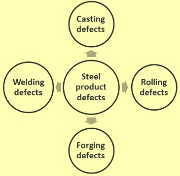
Fig 1 Metallurgical processes and steel product defects
Casting defects
Casting is a forming process which converts liquid steel into a solid product. In foundries liquid steel is cast into complex shapes by pouring of liquid steel into a mould in which it sets to the required shape. In steel plants, liquid steel is normally continuously cast in the form of slab (either thick or thin), bloom or billets. Casting defects are defined as those characteristics which create a deficiency or imperfection exceeding quality limits imposed by design and service requirements.
Defects in foundry cast steel products
There are in general three broad categories of defects in the foundry cast steel products. These are (i) the major or most severe defects which result in scraping or rejection of castings, (ii) intermediate defects which permit salvaging of castings through necessary repairs, and (iii) minor defects which can be easily repaired. Common defects which generally occur in castings are given below.
- Porosity – It consists of the spherical holes of varying size, with bright walls, usually evenly distributed and formed due to the gases in the liquid steel. The larger holes are tend to be found in the heavier section (i.e. last to solidify). If the gas content of liquid steel is low prior to casting then the pinhole type of porosity appears due to absorption of hydrogen (H2) from steam in the mould.
- Blowholes – Blowholes are mainly found in three forms namely (i) elongated cavities with smooth walls, found on or just below the surface of the top most part of castings and are caused by the entrapped air, (ii) round shaped cavities with smooth bright walls which are caused by mould or core gases, coupled with insufficient permeability or venting, and (iii) small cavities immediately below the ‘skin’ of the casting surface which are formed by the reaction of the liquid steel with the moisture in the moulding sand.
- Piping – This is the defect encountered in risers or within the casting proper.
- Inclusions – These are material discontinuities formed by the inclusion of oxides, dross, and/or slag in a casting. They are due to either careless skimming and pouring, or the use of a dirty ladle, or turbulence because of improper gating methods. Faulty closing of moulds can cause ‘crush’ and loose pieces of sand becoming incorporated in the casting.
- Sponginess – it is a defect which occurs during the early stages of solidification of a casting and has the appearance, as the name imply, of a sponge. It is usually local or general in extent. The major cause is failure to obtain directional solidification of the casting towards the desired heat centres, such as risers and ingates, insufficiently high pouring temperature and placing of ingates adjacent to heavy sections.
- Shrinkage – It is a casting defect which occurs during the middle and later stages of solidification of the cast steel. It has a branching formation. It is readily distinguishable from that of sponginess and is in form of void.
- Hot tears – These are discontinuities which result from stresses developed close to the solidification temperature while the steel is still weak. These are attributed to the resistance of the mould and the core, which hinder contraction of the casting, causing thermal stress. Hot tears resemble ragged cracks.
- Crack – Crack is well defined and normally straight. Cracks are formed after complete solidification of the liquid steel. Quite large stresses are needed to cause fracture, and the walls of such cracks are discoloured according to the temperature of the casting when the cracks are formed. Bad casting design coupled with restriction of contraction by the mould, core, or box bars contribute to the cracking.
- Cold shuts – These are discontinuities (a form of lack of fusion) caused by the failure of a stream of liquid steel to unite with another stream of liquid steel, or with a solid steel section such as a chaplet. They are linear in appearance, with perhaps a curling effect at the ends. A cold shut is caused by the fluidity of the liquid steel being too low (i.e. too cold surfaces) or perhaps unsatisfactory methods of feeding the liquid steel.
- Unfused chaplet – A chaplet is often used to support a section of a mould or a core within a mould and when the liquid steel is poured in the chaplets, they are to fuse into the casting. When unfused, the chaplet causes a discontinuity in the casting.
- Misplaced core – It is an irregularity of wall thickness, e.g. one wall thicker than the other, It is caused by core out-of- alignment, careless coring-up and closing of mould, or rough handling after the mould is closed.
- Segregation – Segregation is a condition resulting from the local concentration of any of the constituents of the steel. The segregation can be ‘general’ extending over a considerable part of a casting, ‘local’ when only the shrinkage voids or hot tears are wholly or partially filled with a constituent of low melting point or ‘banded’ which is mainly associated with centrifugal castings but can also occasionally occur in static castings.
Defects in continuous cast steel products
Defects of the continuous cast steel products are formed due to several factors which include material related factors, casting speeds and temperatures, mould oscillation, casting powder, segregation coefficient of solute elements, phase transformation, and mechanical and thermal stresses. Common defects in steel which occurs during the continuous casting are as follows.
- Longitudinal cracks – They are formed in the direction of extraction of the steel. The presence of these defects results into the rejection of the steel. Longitudinal cracks occurs mainly due to (i) uneven primary cooling in the mould, (ii) turbulent flow of liquid steel and a meniscus level variation in the mould, (iii) non uniform or very intensive secondary cooling, (iv) variance in thermal conductivity coefficient along the mould length causing unequal, advanced wear of the mould, (v) casting of liquid steel with high superheat, (vi) high speed of casting, and (vii) use of the casting powder with improper characteristics.
- Transverse cracks – These cracks usually appear due to the tensions in the longitudinal direction of the strand. The transverse cracks are usually ground within the permissible limits provided they are not deep. These cracks appear due to (i) the thermal stresses, (ii) variation in the meniscus level, (iii) presence of segregation at the bottom of oscillation mark, and (iv) friction of the strand in the mould.
- Corner cracks – These are cracks present in the edge of the cast steel product. They appear due to high temperature variations in the liquid steel, higher aluminum content in the steel, higher sulphur level in the steel, non-uniform edge temperature, excess friction in the edges during casting because of non-uniform distribution of casting powder, and lower superheat of the steel.
- Star cracks – These cracks are very fine and caused by fragile nature of the strand at high temperatures. They are visible only on scale free surface. The surface is usually ground locally to remove the defect. Intense local cooling and presence of copper at the austenitic grain boundary cause star cracks. To avoid the star cracks in the cast product it is necessary to have (i) correct correlation between the spray flow and the casting speed, (ii) a uniform layer of melted casting powder between the strand and the mould, and (iii) adequate secondary cooling of the strand for avoiding increase of the thermal stress.
- Depressions – These are local deformations in the cast surface. Depressions can be longitudinal or transverse. Longitudinal depressions appear like the shallow ditches oriented along the length of the cast product. They occur due to the uneven heat transfer in the mould. These depressions can be controlled by uniform cooling in the mould, by centering of the liquid steel jet in the mould, by controlling the fluctuations of the mould steel level, use of a casting powder with suitable viscosity and melting characteristics, and by regularly monitoring the degree and uniformity of the mould wear. Transverse depressions may occur cyclically along the strand length. The peritectic steels with low carbon and high manganese contents and the stainless steels are sensitive to this defect. The transverse depressions can be caused by the fluctuations in the mould level, large quantity of casting powder, and by the turbulence of steel the sub-meniscus level. These depressions are controlled by controlling the mould steel level, having proper mould taper, use of a casting powder with suitable viscosity and melting characteristics, and proper positioning of the input nozzle and its support.
- Blowholes – These are cavities in the outer surface of the cast product and are often associated with inclusions. They are caused by presence of gases in the steel, humidity and quality of the casting powder, variation in the mould level, presence of moisture in the tundish refractory lining. Blowholes are controlled by sufficient de-oxidation of steel, use of dry casting powder, use of casting powder compatible with the grade of steel grade, temperature and casting speed, control of mould level fluctuations, control of nozzle immersion depth, avoiding the high superheat and avoiding slag foaming around the nozzle.
- Interruptions in the physical continuity of the cast product – This defect occurs when there is a pause in the casting process. It often occurs when there is a change of heat during sequence mode of operation. This defect is caused by a short interruption of the casting process and occurs when there is sudden change in casting speed caused by the variations of steel temperature in the tundish, by the variations of steel level in the mould, cogging of the nozzle due to high alumina levels, or by the variations of casting mode. The corrective measures are maintenance of a constant casting speed, a narrow range of temperature variation in the tundish, and steel level in the tundish within the prescribed limits.
- Slag spots defects -This defect is caused by the penetration of tundish slag in the cast product. It is caused by high level of slag in the tundish, rise in the active oxygen percentage in the steel, lowering of steel level in the tundish resulting in slag to enter the mould, and high viscosity of casting powder.
Rolling defects
The common rolling defects of steels are given below.
During the hot rolling, if the temperature of the steel is not uniform then the flow of the material occurs more in the areas having higher temperature and less in the parts with lower temperature. High temperature difference results into cracking and tearing.
In flat steels, the flatness is a characteristic describing the extent of the geometric deviation from a reference plane. The deviation from complete flatness is the direct result of the steel relaxation after hot or cold rolling, due to the internal stress pattern caused by the non-uniform transversal compressive action of the rolls and the uneven geometrical properties of the steel being fed for the rolling. The transverse distribution of differential strain/elongation induced stress with respect to the material’s average applied stress is normally termed as shape. Due to the strict relationship between shape and flatness, these terms are generally used in an interchangeable manner. In the case of steel strips and sheets, the flatness reflects the differential elongation across the width of the steel.
Profile is made up of the measurements of crown and wedge. Crown is the thickness in the centre as compared to the average thickness at the edges of the steel strip or sheet. Wedge is a measure of the thickness at one edge as opposed to the other edge. Both are generally expressed as absolute dimensions or as relative dimensions. As an example, the steel piece can have a crown of 0.05 mm (the centre of the steel is 0.05 mm thicker than the edges), or the steel piece can have 2 % crown (the centre of the steel piece is 2 % thicker than the edges). It is typically desirable to have some crown in the steel piece since it causes the steel piece to tend to pull to the centre of the rolling mill, and thus the rolling takes place with higher stability.
Mill spring is a defect in which the rolled sheet is thicker than the required thickness because, the rolls have got deflected by high rolling forces. Elastic deformation of the mill takes place. If stiffer rolls are used, namely roll material of high stiffness or elastic constant, then mill spring can be avoided. Normally elastic constant for mills may range from 1 to 4 GN/m. Roll elastic deformation can result in uneven strip thickness across. Roll material is to have high elastic modulus for reducing the roll deformation.
Maintaining a uniform gap between the rolls is difficult since the rolls deflect under the load required to deform the steel piece. The deflection causes the steel piece to be thinner on the edges and thicker in the middle. This can be overcome by using a crowned rolls (parabolic crown), however the crowned rolls only compensate for one set of conditions, specifically the material, temperature, and amount of deformation. Other methods of compensating for roll deformation include continual varying crown (CVC), pair cross rolling, and work roll bending. Another way to overcome deflection issues is by decreasing the load on the rolls, which can be done by applying a longitudinal force which is essentially drawing. Other method of decreasing roll deflection includes increasing the elastic modulus of the roll material and adding back-up supports to the rolls.
Flatness of rolled steel sheets depends on the roll deflection. Sheets become wavy as roll deflection occurs. If rolls are elastically deflected, the rolled sheets become thin along the edge, whereas at centre, the thickness is higher. Similarly, deflected rolls result in longer edges than the centre. Edges of the sheet elongate more than the centre. Due to continuity of the sheet, the centre is subjected to tension, while edges are subjected to compression. This leads to waviness along edges. Along the centre zipper cracks occur because of high tensile stress there. Cambering of rolls can prevent such defects. However, one camber works out only for a particular roll force. In order to correct roll deflection for a range of rolling conditions, hydraulic jacks are used, which control the elastic deformation of rolls according to the requirement.
Edge cracks occur if rolls have excess convexity. They occur when the centre of the steel sheet has more elongation than the edges. This leads to a defect called centre buckle. Edge defects are due to heavy reduction. Small thickness sheets are more sensitive to roll gap leading to greater defects. Thin strips are more likely to undergo waviness or buckling.
During rolling, the steel sheet has a tendency to deform in lateral direction. Friction is high at the centre. Therefore, spread is the least at the centre. This leads to rounding of ends of the sheet. The edges of the sheet are subjected to tensile deformation. This leads to edge cracks. If the centre of the sheet is severely restrained and subjected to excess tensile stress, centre split can happen. Non-homogeneous material deformation across the thickness leads to high secondary tensile stress along edge. This leads to edge cracks. Secondary tensile stresses are due to bulging of free surface.
Due to non-homogeneous flow of material across the thickness of the steel sheet, another defect called allegatoring occurs. This is due to the fact that the surface is subjected to tensile deformation and centre to compressive deformation. This is because greater spread of material occurs at the centre.
The different classifications for flatness defects are as below.
- Symmetrical edge wave – the edges on both sides of the steel piece are ‘wavy’ because of the steel material at the edges are longer than the material in the centre.
- Asymmetrical edge wave – one edge is ‘wavy’ because of the steel material at one side is longer than the other side.
- Centre buckle – The centre of the strip is ‘wavy’ because of the strip in the centre is longer than the strip at the edges.
- Quarter buckle – This is a rare defect where the steel grains are elongated in the quarter regions (the portion of the strip between the centre and the edge). This is normally due to the use of excessive roll bending force since the bending force may not compensate for the roll deflection across the entire length of the roll.
Surface defects are (i) lap which appears as seam across the surface of the metal and occurs when a corner or fin is folded over and rolled but not welded into the metal, (ii) mill shearing which occurs as a feather-like lap, (iii) rolled in scale which occurs when mill scale is rolled into the steel, (iv) scabs which are long patches of loose metal that have been rolled into the surface of the steel, (v) seams which are open, broken lines that run along the length of the rolled steel and caused by the presence of scale as well as due to pass roughness of roughing mill, and (vi) slivers which are prominent surface ruptures.
Seams are surface irregularities, such as cracks, on the semi-finished steel which are stretched out and lengthened during rolling. Seams can also be caused by folding of the steel due to improper rolling. Seams are surface discontinuities and on finished bars they appear as either continuous or broken straight lines. On round bars they appear as straight or slightly spiral lines, either continuous or broken.
Laminations are large porosity, pipe and non-metallic inclusions in the semi-finished steel which are flattened and spread out during the rolling process.
Stringers are non-metallic inclusions in semi-finished steel which thinned and lengthened in the direction of rolling by the rolling process.
Forging defects
Discontinuities in forgings can originate from the defects in the slab, bloom, or billet being forged. These defects are modified during the forging of the material. The discontinuities can also result from the forging process itself. Some of the defects that can occur in forgings are similar to those in castings. Some specific defects of forgings are given below.
- Laminations – These are large porosity, pipe and non-metallic inclusions in slabs, blooms, or billets which are flattened and spread out during forging process.
- Forging laps – These are the discontinuities caused by the folding of metal in a thin plate on the surface of the forging. They are irregular in contour.
- Centre bursts – These are ruptures which occur in the central region of a forging. They can arise because of an incorrect forging technique (e.g. very low temperature or drastic reduction) or because of the presence of segregation or brittle phase in the steel being forged.
- Clinks (thermal cracks) – They are cracks due to stresses arising from excessive high temperature gradients within the material. Cracks formed during too rapid cooling originate at the surface and extend into the body of the forging while those formed during too rapid heating occur internally and can be opened up to become diamond-shaped cavities during subsequent forging.
- Hairline cracks (flakes) – These are very fine internal cracks of circular shape. They develop and extend with time and are associated with the presence of hydrogen in steel. There is greater susceptibility in larger forgings than in smaller forgings and in certain grades of alloy steel than in carbon steel. They can be avoided by proper treatment.
- Hot tears – These are surface defects due to the steel being ruptured and pulled apart during forging. They are normally associated with the presence of local segregation, seams, or brittle phases.
- Overheating – It is normally identified by the facets seen on the fractured surfaces of a test-piece, but in extreme cases, can manifest itself as a severely broken-up surface.
- Pipe – In case of forging of ingot, if there has been insufficient discard from the original ingot, remnant primary pipe normally show up axially. Secondary pipe which has never been exposed to the atmosphere gets welded-up if there is sufficient forging.
Welding defects
During the process of welding, various types of defects can occur. Some defects are due to the quality and hardness of the weld metal, while others are due to lack of skill of the welder. The most common defects occurring during welding are given below.
- Porosity – Molten weld metal has a considerable capacity for dissolving gases which come into contact with it such as hydrogen, oxygen and nitrogen. As the molten weld metal cools its ability to retain the gases reduces. With the change from the liquid to the solid state, there is reduced solubility with falling temperature. This causes evolution of gas at a time when the metal is becoming mushy and therefore incapable of permitting the gas to escape freely. Entrapment of the gas causes gas pockets and porosity in the final weld. The porosity can be of three types namely (i) fine porosity, (ii) blow holes, and (iii) piping. Fine porosity consists of small bubbles of gas usually of diameter less than 1.5 mm. Blow holes are usually gas pores larger in dimension while ‘piping is an elongated or tubular cavity. Piping is usually almost perpendicular to the weld surface. It can result from the use of wet powdered flux or from inadequate control of the welding current. Another typical form of pipes has the appearance of a branch of a tree. Porosity may be scattered uniformly throughout the weld, isolated in small groups, or concentrated at the root of the weld. Various causes of porosity include excessive moisture content of the electrode covering, incorrect electrode current, defective gas shielding, contamination of joint surface or filler wire, and rapid cooling of the weld metal or the composition of the electrode core wire or parent steel.
- Non-metallic inclusions – These are the result of weld metal contamination by substances on the surface of the joint or by the atmosphere. However, the normal source is the slag formed by the electrode covering or flux used in the welding process. Some slag is trapped in the deposited metal during its solidification, particularly if the metal fails to remain liquid for a sufficient period to permit the slag to rise to its surface. In multi-pass welding, insufficient cleaning between weld passes can leave a portion of the slag coating in place to be covered by subsequent passes. A particular characteristic of slag inclusions is the ‘slag line’, intermittent or continuous. Such slag lines are frequently accompanied by a pronounced lack of fusion to the base steel. In general, inclusions can be due to any one of several reasons which include (i) failure to clean the surface of the joint, (ii) failure to remove slag from a previous deposit, (iii) incorrect edge preparation, (iv) incorrect handling of the electrode, (iv) insufficient arc shielding, and (v) improper rate of cooling.
- Tungsten inclusions – These are particles of metallic tungsten embedded in the weld metal which originate from the tungsten electrode used in tungsten arc welding. Causes are excessive welding current allowing the melting and deposition of tungsten in the weld and incorrect polarity of electrode using a DC source. Tungsten inclusions can also be caused from dipping the electrode into the molten weld metal or by touching the filler rod to the electrode during welding. Tungsten inclusions normally occur at the start of welds when the electrode is usually cold. Small globular and widely scattered tungsten inclusions are sometimes permissible, but sharp edged inclusions are dangerous.
- Lack of fusion – This is due to the lack of union in a weld between the weld metal and parent steel or between parent steel and parent steel or between weld metal and weld metal. Hence, the lack of fusion can be of three types namely (i) lack of side fusion, (ii) lack of root fusion and (iii) lack of inter-run fusion. The defect results mainly from (i) the presence of slag, oxides, scale, or other non-metallic substances, (ii) too low a welding current, or (iii) incorrect edge preparation. Incomplete fusion can also arise from too high a welding current when the high rate of melting encourages the welder to use excessive welding speed. The defect greatly reduces the strength of a joint subjected to static loading and under cyclic or shock loading which is quite serious.
- Incomplete root penetration – In butt welding, a root opening is usually left at the bottom of the groove (in single side welding) or at the centre of the weld (in two-side welding). If the opening between the two plates is narrow, it is difficult to achieve complete penetration and fusion at the root of the weld. Hence there can be a lack of fusion in the root of the weld or a gap left by the failure of the weld metal to fill the root of a butt weld. It is caused by the electrode held at an incorrect angle, an electrode too large in diameter, a rate of travel too fast, an insufficient welding current, or an improper joint preparation (e.g. joint misalignment).
- Cracks – These are defined as a discontinuity produced either by tearing of the steel while in a plastic condition (hot crack) or by fracture when cold (cold crack). Cracks can occur in either the weld metal or parent steel. In weld metal they are classified as longitudinal, transverse, crater, and hairline cracks. In the parent steel, it is cracking in the parent plate with the origin in the heat-affected zone of the weld. The strength of a welded joint under any conditions of loading is seriously reduced by the presence of a crack. Weld metal cracks are caused by high localized stresses in the joint arising from the shrinkage of weld metal, by resistance of movement of the parts, or by vibration of the structure during welding. Hence, it is important that each weld run is strong enough to withstand the shrinkage and allows as much freedom of movement as possible. Longitudinal weld cracks usually occur in the root run and, if left as such, will eventually propagate through subsequent runs. Incorrect finishing of a weld run can form a crater and possibly lead to a crater crack. Parent steel cracking is associated with the welding of medium carbon and alloy steels. A considerable amount of work has been done into the techniques for welding these steels and it is most important that instructions regarding type and condition of electrode, the degree and extent of preheat and the restrictions on size of single pass welds are strictly followed to avoid this form of cracking.
- Undercut – During the final or cover pass the exposed upper edges of the bevelled weld preparation tend to melt and to run down into the deposited metal in the weld groove. The result is a groove which may be either intermittent or continuous, with more or less sharp edges along the weld reinforcement.
- Concavity at the root of the weld – A concave surface at the root of the weld can occur specially in pipe welding (without a cover pass on the root side). In overhead welding this condition is a consequence of gravity which causes the molten metal to sag away from the inaccessible upper surface of the weld. It can also occur in down-hand welding with a backing strip at the root of the weld groove if slag is trapped between the molten metal and the backing strip.
- Excessive penetration – In welds molten metal sometimes runs through the root of the weld groove producing an excessive reinforcement at the back side of the weld. In general this is not continuous but has an irregular shape with characteristic hanging drops of excess metal.
- Overlap – it is an imperfection at the toe or root of a weld caused by an overflow of weld metal onto the surface of the parent metal, without fusing with the latter. It is caused when the welding rod has been used at an incorrect angle, the electrode has travelled too slowly, or the current was has been low.

Leave a Comment