Historical aspects of the Continuous Casting and related Technologies for Steel
Historical aspects of the Continuous Casting and related Technologies for Steel
Continuous casting (CC) technology of steel, as a method of solidification processing of liquid steel has a relatively short history —not much longer than oxygen steelmaking. Different to other processes in steel production, continuous casting is the vital link between the liquid and the solid phase and has to live with metallurgical effects as well as mechanical challenges at the same time.
Continuous casting transforms liquid steel into solid on a continuous basis and includes a variety of important commercial processes. These processes are the most efficient way to solidify large volumes of liquid steel into simple shapes for subsequent processing. The CC ratio for the world steel industry is now around 96 % of crude steel output which was a mere 4 % in 1970.
Continuous casting is distinguished from other solidification processes by its steady state nature. The liquid steel solidifies against the mould walls while it is simultaneously withdrawn from the bottom of the mould at a rate which maintains the solid / liquid interface at a constant position with time. The process works best when all of its aspects operate in this steady-state manner.
Relative to other casting processes, continuous casting generally has a higher capital cost, but lower operating cost. It is the most cost- and energy- efficient method to mass-produce semi-finished steel products with consistent quality in a variety of sizes and shapes. Cross-sections can be rectangular, for subsequent rolling into plate or sheet, square or circular for long products and seamless pipes, and even dog-bone shapes, for rolling into I or H beams.
Today continuous casting machines consist of modularized technological/mechatronic packages to allow fast design and short project execution time as well as rapid production ramp-up after the first heat has been cast. From the metallurgical point of view state-of-the-art continuous casting machine have features to enable strand treatment through special cooling and soft reduction technologies. Sophisticated process models allow on-line process simulation and close loop control to further optimize product quality and productivity goals. Robotic units perform tasks in hazardous areas and improve operational reliability without human intervention. The speed of innovation has been outstanding in continuous casting since its start of commercialization in the 1950s. Visions and the first attempts of development of this process during 1960s and 1970s as well as benchmarks in the 1980s are observed.
During the rather lengthy incubation in the precursory periods, i.e., before the 1950s, important development stimuli came from the nonferrous industry, which had applied CC processes already—in particular, by the travelling mould principle—using casting wheels and/or belts to overcome mould friction. Later, genuine ideas emanating from steelmakers added various milestones to the driving of CC application to steel, albeit primarily by a process based on a stationary, oscillating mould.
Early stages in the development of continuous casting
The idea of making the casting process more productive through continuity is attributed to J Laing who in 1843 patented in USA after successfully testing of a machine for horizontal continuous casting of tubes and sheets from low melting metallic alloys. In this patent Laing proposed feeding of the liquid metal from a vertical reservoir through a trough to a preheated horizontal mould with an inserted mandrel that rotated around its axis to prevent sticking to the casting. The tube was cooled at the exit from the mould.
Further development of continuous casting is ascribed to Henry Bessemer who in 1857 suggested and patented in UK a device known as twin roll caster. In this device, liquid steel was poured between two water cooled drums, and the resultant solid sheet was extracted through curved guide plates where the sheet was continuously cut to measure, and further extracted through spring loaded rolls (Fig 1). However Bessemer did not pursue this technology presumably giving higher priority to developing the steelmaking process first.
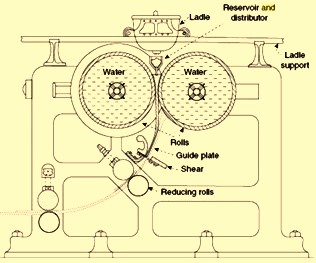
Fig 1 Continuous casting process proposed by Henry Bessemer
It took more than 100 years for the continuous casting of steel to become a mass production technology, but then with a different design than that of the twin roll casting which has been applied to light alloys on the industrial scale.
In such further developments, Bessemer then implemented a tundish with stopper for slag retention. The 250 mm x 250 mm mould below the tundish incorporated a hydraulic ram to push the ingot upward for an intended direct rolling of ingot without reheating. This was a precursor for closing the lower end of the mould with a dummy bar.
Goeran Fredrik Goeransson of Sweden introduced a stoppered ladle for the transfer of liquid steel from the blowing vessel to the pouring pit via a hoist in 1858. This was replaced by Henry Bessemer in 1859 with a swing type device which was the first ladle turret. The first ladle slide gate was conceived in 1885 by David D Lewis.
The next step in the development of the continuous casting was made by Benjamin Atha in 1886. As per his patent application the high, water cooled, bottomless mould was directly connected with the tundish while the dummy bar featured a claw shaped head and extracting the resultant metal billet intermittently with driven withdrawal rolls. The method was used for semi commercial production of billets of size 100 mm square in the beginning of the twentieth century, but did not make it to mass production. Independently RM Daelen patented in 1889 a similar (not actually used) apparatus with shear cutting on the fly.
The first caster built by a genuine machine builder, Arthur McKee Co. of Cleveland, Ohio, in 1915 had been designed by John T Rowley of USA already with bending and unbending and with billet sizes of 45 mm x 45 mm to 75 mm x 75 mm in lengths ranging from 10 m to 50 m (without cut off on the fly). There was erratic length control as a consequence of excessive mould friction which caused shell sticking and tearing at random.
The concept to reciprocate a short mould up and down to reduce mould friction was patented by Cornelius W. van Ranst of US in 1921. Siegfried Junghans of Germany first time implemented mould oscillation in the 1930s. His continuous casting machine was initially used at Wieland-Werke for the casting of brass. The mould consisted of a copper tube open at both sides and surrounded by a water jacket. The liquid metal was fed from the top, and the solidified metal was withdrawn by rolls from the bottom. By a special system, the liquid metal feeding was adjusted to the withdrawal speed in such a way that the liquid metal level was maintained constant in the mould. This was important part of the technology and a vivid example that the CC process offers an advantage of automation and control. The mould was lubricated and given an up and down oscillating movement to prevent sticking of the solid metal to the mould walls. This feature was eventually adopted for the continuous casting of steels. Flying saws were positioned in the pit below the installation for the continuous cutting of the billets into the required length. Such a scheme had been successful and was widely used for the continuous casting of copper, and aluminum alloys in Germany, USA, and the then USSR. The Junghan process was applied to magnesium from 1937 onwards for the casting of 200 mm diameter round billets for extrusion and slabs of dimensions up to 100 mm x 600 mm. Fig. 2 depicts the Junghans method of continuous casting. Later on, Junghans added water spraying directly on the billet and made many innovations regarding the proper liquid metal feeding and distribution system.
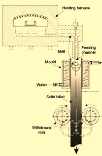
Fig 2 Junghan’s method of continuous casting
As compared with the permanent mould casting used before, the Junghans method had the following advantages.
- Truly continuous process with possibility of advanced automation which allowed increased productivity with less manpower
- Reproducible casting regimes that allowed reproducible quality of billets
- Better feeding of the central portions of billets with correspondingly increased soundness of billets
- More uniform structure across the billet
- Better removal of gases during casting through the liquid portion of the billet
- Lesser scrapped material
However Junghans method did not solve all the problems of permanent mould casting, mainly due to the heat extraction being predominant through the walls of the mould. As a result, the sump of the billet was deep, the solidified shell was subject to high thermal gradients, and the air gap formation required the maintenance of low casting speeds or, in other words longer solidification times. Larger billets (300 mm – 500 mm in diameter) were characterized with inhomogeneous structure and chemical composition (macro-segregation). The long moulds which were necessary for proper cooling called for very fine finish of the internal surface.
In order to eliminate these shortcomings, it was necessary to develop a technology, where the heat would be extracted predominantly through the solid part of the casting. As a result, the sump of the casting needed to be shallower with the solidification profile required to be flatter. The macro segregation, structure in-homogeneity, and radial stresses needed to be much less pronounced. These needs were met with a new technology developed almost simultaneously and independently in Germany and USA. This technology is known as ‘direct chill (DC) technology’. This technology was soon commercialized and was used on industrial scale. The DC casting process as per the technology was as follows.
Liquid metal was poured from the top in an open, relatively short water cooled mould, which in the beginning was closed from the bottom by a dummy block connected with a hydraulic or mechanical lowering system. After the melt level in the mould reached a certain level, the ram was lowered and the solid part of the billet was extracted downwards. The liquid metal flow rate and the casting speed were adjusted in such a way that the liquid level in the mould remained constant. As soon as the solid shell emerged from the bottom part of the mould, water was applied to the surface in a form of spray or water film. Cooling of the solid billet was further intensified by lowering it into a pit filled with water (which also made the process safer, as liquid metal, in case of a bleed out, was rapidly cooled in a large amount of water). The process was semi-continuous. As soon as the ram reached its lowest position in the pit, the casting was stopped, and the billet was removed from the pit. DC casting had a unique feature that makes it very distinct from previously used casting technologies.
The solidification occurred in a narrow layer of the casting inside and below the mould. During the steady stage of casting, the shape and the dimensions of this region remained constant and reproducible from one heat to another. By controlling the liquid metal distribution during feeding the mould, direct cooling below the mould, and the casting speed, the shape and the dimensions of the solidification regions could be maintained within the optimum limits. As these shape and dimensions determine the thermal gradients and are responsible for cracking, macro segregation, and structure homogeneity, the occurrence of these defects could also be controlled. DC casting had the following advantages over Junghans method of casting.
- Considerably reduced centerline segregation
- Increased density of the central portion of the billet
- Finer and more homogeneous structure with correspondingly improved mechanical properties
- Better surface quality
- Lower operation cost
The first CC machine for non-ferrous metal was installed by Rossi, an entrepreneur, in 1937 at Scovill Manufacturing Co. at Waterbury applied several CC processes of that time. The continuous caster (Fig 3), with oscillating mould plus direct cooling with water sprays below looked rather simple but an elaborate system for the supply and feeding of the liquid metal was implemented. These included (i) fully shrouded liquid metal transfer from the ladle through a funnel into two induction heated and inertized holding vessels, arranged in parallel, (ii) from there, shrouded liquid metal transfer into a small and inertized intermediate feeding trough by inert gas pressure (assuring complete slag retention) via resistance heated ducts, and equipped with a metal height indicator, and (iii) then, gravity feed of liquid metal through another resistance heated duct into the gas shrouded mould. Rossi had guaranteed an uninterrupted caster operation of seven days which was achieved from very start of the continuous caster.
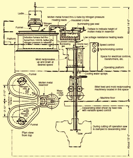
Fig 3 Rossi caster with oscillating mould
Stimulated by this successful example of the nonferrous industry, efforts gradually got intensified to apply CC technology to steel too. However, most of such developments were heavily curtailed in the years during and shortly after world war two. Very few details and operational details surfaced during this period due to the environment of general secrecy during the period. Edward R. Williams, president of ‘Vulcan Mold and Iron Co.’ went for a long and stationary mould and attempted to reduce mould friction by intermittent strand withdrawal. His patent application included a roller apron strand support required in the casting of a slab sections. He along with Republic steel started a large pilot caster in 1942 for billets of size 100 mm x 100 mm as well as mini slabs of size 75mm x 215 mm. A further pilot unit was built with Babcock and Wilcox in 1948 which was equipped with such advanced features as automatic mould level control and TV supervision.
Based on a stationary fixed mould, many similar contemporary efforts were initiated then in USA, in Great Britain, in Russia (then USSR), in Japan, in Austria, and in France. These casting efforts were impaired by mould friction and hence were less successful than early pilot casting of steel with the oscillating Junghans- Rossi mould. In 1949 Junghans started his own pilot caster, fed by I ton Bessemer converter. After starting the caster he entered a cooperation agreement with Mannesmann, who started their pilot caster at Huckingen in 1950. In 1952, the German and the Austrian CC developers joined forces, later nominating Demag as their machine builder in 1956, which led to the group acronym DMB, Demag- Mannesmann- Boehler.
Rossi who was left on his own, supplied his first steel casting machine, built by Koppers Co. which was started at Allegheny Ludlum in 1949. This caster was for billet section of round of size 150 mm diameter and mini slab of size 75 mm x 380 mm. Rossi gave guarantees for caster productivity of 20 tons per hour as well as for product quality. This caster is being considered as the very first attempt at a commercial caster for steel. The caster is shown in Fig 4. Other than the features seen in the Fig 4, this caster had inert gs shrouding of tundish and mould as well as resistance preheating of the non-submerged pouring tube. For eventual application of a submerged entry nozzle (SEN) to thin slab section, Rossi proposed and patented a funnel shape upper mould half but he did not use it.
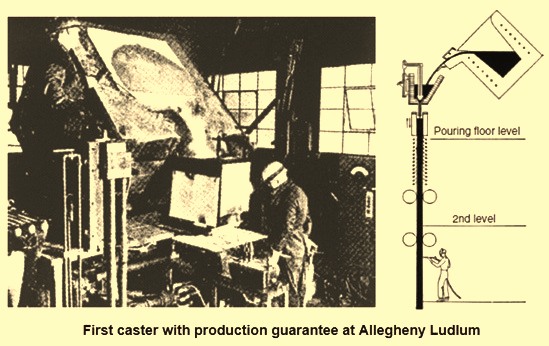
Fig 4 First caster with production guarantees
Rossi formed the engineering company ‘Continuous Metalcast Inc. with Allegheny and Koppers among shareholders and received four more orders from specialty steelmakers in USA, England, Sweden and France. For handling overseas business, Concast AG, Zurich, Switzerland was founded by Rossi in 1954. Thus two major rival groups emerged in caster design and supply at the onset of CC industrialization, other than many machine building efforts of smaller capacity. A certain understanding between the two groups was reached after the implementation of curved mould concept when both DMB consortium and the Concast group formed a joint venture company in 1963 called MBC (Mannesmann- Boehler- Concast) in Zurich.
Initially CC development in steel was focused on the manufacture of the specialty steels where potential yield savings entailed the largest cost advantage. Also smaller ladle capacity was more compatible with lower caster throughput rate. Further obstacle for adopting of continuous casting by large producers was because of unsuccessful attempts in producing rimming steels of acceptable surface qualities. Thus early efforts in slab casting were restricted to the production of manganese-silicon (Mn-Si) killed plate grades of steels. Only the conversion to aluminum (Al) killed steels and parallelly improvements in strand surface qualities opened the way to wider application of continuous casting for both flat and long products. In this regards, developments in secondary steelmaking also became a vital prerequisite, equally important both for caster productivity and product quality.
In the course of the development of the continuous casting machines, several types of casters have been realized with significant difference in design heights (Fig 5). Some of these types were having restricted caster productivity either due to limited support length (vertical casters) or due to casting speed limited by high mould friction (horizontal casters). Besides, there were also characteristics differences with respect to the product quality.
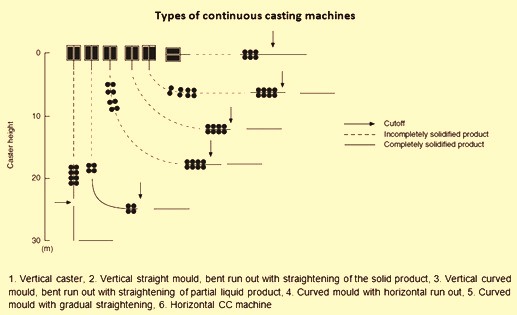
Fig 5 Types of continuous casting machines
The vertical casting machine was the natural machine design, casting with gravity and also assuring a symmetric macrostructure; but caster productivity was severely limited by machine height. Hence, several efforts in CC history were noteworthy to extend machine length at low building height by strand bending and straightening, e.g. the billet caster by Rowley and a more advanced proposal by Tarquinee and Scovill. To prevent inner cracking, several rules for caster design, based on critical strain and strain rate at the solid/liquid interface had been developed which has led to distinct bending and straightening zones extending over several roller pairs.
With the advent of the curved mould casting principle, introduced simultaneously by the pioneering plant trials at Mannesmann Huckingen and Von Moos Stahl in 1963, the required building height was substantially reduced. This caster type initiated rapid growth of CC application in case of continuous casting of billet and blooms, especially in small billet casting shops that could use the existing buildings. In slab casting, however, the widespread use of curved mould design came to a clear halt in recent years on account of the accentuated quarter-band accumulation of macro-inclusions and/or argon bubbles. Hence apart from new casting machines now being exclusively built as straight mould/bending type, existing curved mould machines are increasingly being revamped.
From the beginning of CC development, a major concern was liquid steel temperature control. This was a major obstacle for small ladle capacities with large surface to volume ratio. While early pilot casters were directly fed from the melting or holding furnaces, this was not practical for a large scale operation. One earlier approach pursued by Halliday at Barrow steel works in England in this direction was use of a completely enclosed lip pour ladle which could be heated during casting by a can-jet burner through the ladle lid, allowing casting time up to 2 hours from a 7 ton ladle. Halliday also insisted on high temperature ladle preheating. For larger capacities, lip pour ladles were not practical so ladles with stopper flow control were introduced. However, the use of stopper control was not well suited to the increasing metal residence time. Hence a great advancement in operational reliability and caster productivity was achieved by the implementation of the ladle slide gate.
Since 1980s a large number of developments have taken place to improve the performance of continuous casting technology for steels. These improvements have taken place in ladle treatments of liquid steels, ladle to tundish and tundish to mould transfer of liquid metal, in the tundish (tundish metallurgy), in moulds and primary cooling (electro-magnetic stirring etc.), in secondary cooling and cast metal support (electro-magnetic stirring and air mist cooling etc.), cutting and cooling of the cast steel (turnover type cooling beds), and automation and control of the process. Fig 6 gives typical examples of expert system and electro-magnetic stirring.
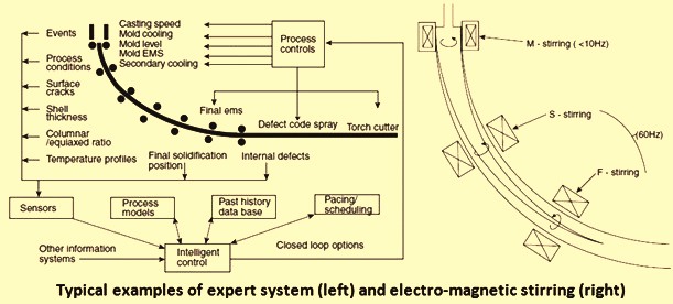
Fig 6 Typical examples of expert system and electro-magnetic stirring

Leave a Comment