Vacuum Degassing Processes for Liquid Steel
Vacuum Degassing Processes for Liquid Steel
During the primary steelmaking process, gases like oxygen (O2), hydrogen (H2) and nitrogen (N2) dissolve in the liquid steel. These gases have a harmful effect on the mechanical and physical properties of steel. Dissolved O2 from liquid steel cannot be removed as molecular O2 and its removal is termed as deoxidation. The term degassing is used for the removal of H2 and N2 gases from liquid steel. Since the degassing process of liquid steel is carried out under vacuum, it is also known as vacuum degassing of liquid steel. Vacuum degassing processes are carried out in steel teeming ladles.
Removal of H2 and N2 gases from liquid steel is necessary since both of these gases harm the properties of steel. Solubility of H2 in steel is low at ambient temperature. Excess H2 is rejected during solidification and results in pinhole formation and results into the porosity in solidified steel. Few ppm (parts per million) of H2 gas causes blistering and loss of tensile ductility. In case of N2 gas, maximum solubility of N2 in liquid iron is 450 ppm and less than 10 ppm at room temperature. During solidification excess N2 is rejected which can cause formation of either blow holes or nitrides. Excess N2 also causes embrittlement of heat affected zone during welding of steels and also impairs cold formability of steel.
It was only in the early 1950s that the problem of producing steel with minimum gas content was solved through the development of a method of vacuum treatment of liquid steel in the ladle before its teeming. The method was proposed by the scientists AM Samarin and LM Novik of erstwhile USSR in 1940. It was first tried industrially in the then USSR in 1952 at the Enakievskii metallurgical plant. In 1954 in the then Federal Republic of Germany, at the Bochumer Verein, a method of degassing a flow of metal was tried. The industrial introduction of the ladle method of vacuum treatment was first made in the then USSR in 1955. This initiated a new trend in steelmaking known as the vacuum treatment of steel.
The vacuum treatment of liquid steel in the ladle started first with the ladle to ladle and ladle to ingot mould vacuum degassing processes for the removal of H2. Originally vacuum degassing of liquid steel is carried out under reducing condition at a pressure ranging from 0.5 to 10 mbar (1mbar= 0.75 mm Hg or 0.00102 kg/sq cm) with the objective of reducing the H2 content to less than 2 ppm.
In the late 1950s more efficient vacuum degassing processes such as the Dortmund Hoerder (DH) and Ruhrstahl-Heraeus (RH) processes became popular. In the middle of 1960s degassing processes such as vacuum arc degassing (VAD), the ASEA-SKF process, and the vacuum oxygen decarburization (VOD) process for treating high chromium (Cr) steels were successfully implemented.
Initially, the concept of vacuum degassing was used primarily for the removal of H2 gas from liquid steel, but sooner it served many other purposes also for the production of clean steels. Since around 1980 or so there has been an increased use of vacuum degassing for the production of ultra-low carbon (ULC) steels with carbon (C) contents of 30 ppm or less. Furthermore, with the development of interstitial-free (IF) steels with C and N2 contents of 30 ppm or less, a treatment under vacuum has become a necessity. Presently, a vacuum degassing treatment has become an essential facility for a steel melting shop producing quality steel.
The general features of vacuum degasing are as given below.
- Desorption of gases is a gas/metal interfacial reaction. The atomic H2 or N2 from the liquid steel has to diffuse at the gas/metal interface, where it is converted to molecular H2 or N2 which can then be desorbed. The effectiveness of vacuum treatment increases with increase in surface area of liquid exposed to vacuum. The increased surface area of liquid steel exposed to vacuum e.g. in the form of a thin stream or gas induced stirring accelerates the degassing process.
- Temperature of liquid steel drops during vacuum degassing process. More is the surface area of stream exposed to vacuum higher is the temperature drop.
- The degassing time need to be kept at minimum.
- The degree of degassing increases with the degree of vacuum. Vacuum of the order of 1 mm Hg or even less than 1 mm Hg (1 mm Hg=1torr) is employed in the practice. Vacuum pumping capacity is required to be adequate.
Vacuum degassing processes which are presently being used can be classified into the three types namely (i) stream degassing practice, (ii) circulation degassing practice, and (iii) Ladle or tank degassing practice.
Stream degassing practice
In stream degassing, liquid steel is poured into another vessel which is under vacuum. Sudden exposure of liquid stream in vacuum leads to very rapid degassing due to the increased surface area created by break-up of stream into droplets. This process helps the H2 dissolved in steel, to be evacuated by a vacuum pump. The major amount of degassing occurs during the fall of liquid stream. The height of the pouring stream is an important design parameter. Stream degassing technology has following variants in the practice.
- Ladle to ingot mould degassing – Preheated ingot mould with hot top is placed in vacuum chamber. Above the chamber a tundish is placed. Liquid steel tapped in the ladle is at superheat equivalent of 30 deg C. The ladle is placed above the tundish. Bottom pouring of liquid steel is into the tundish is desirable. Schematic of ladle to mould degassing is shown in Fig 1.
- Ladle to ladle degassing – In ladle to ladle degassing, a ladle with the stopper rod is placed in a vacuum chamber. Ladle containing liquid steel from primary steelmaking furnace is placed on top of the vacuum chamber and the gap is vacuum sealed. Alloy additions are made under vacuum. Stream is allowed to fall in the ladle where liquid steel is degassed. Alloy additions are made under vacuum.
In some plants degassing is done during tapping. In this arrangement liquid steel from primary steelmaking furnace is tapped into tundish or small ladle. From the small ladle liquid stream is allowed to fall into a ladle which is evacuated. Ladle is closed from top with a special cover which contains exhaust opening. Liquid steel with 25 deg C to 30 deg C superheat is tapped into ladle.
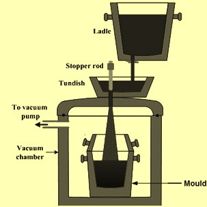
Fig 1 Schematics of ladle to mould degassing
Circulation degassing practice\
In the recirculation degassing practice, liquid steel is allowed to circulate in the vacuum chamber continuously by special arrangement. In this process, a vacuum chamber is positioned above the ladle possessing a snorkel or snorkels which are dipped into the liquid steel bath. There are two types of circulation degassing processes (Fig 2) namely (i) Ruhrstahl – Heraeus (RH) degassing process, and (ii) Dortmund – Hörder (DH) degassing process. RH degassing process has two snorkels dipped into the ladle while DH degassing process has a single snorkel and operates by repeatedly sucking the liquid steel into the vacuum chamber and then releasing it back into the ladle. RH degassing process is described in a separate article given under link http://www.ispatguru.com/rh-vacuum-degassing-technology/.
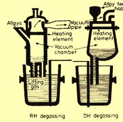
Fig 2 Schematics of circulation degassing processes
In RH degassing process, a cylindrical refractory lined shell with two legs (also called snorkel) is designed such that the liquid steel is raised in one leg and falls back into the ladle after degassing through the second leg. Top side of the cylindrical shell is provided with exhaust, alloy additions, observation and control window. Cylindrical shell is lined with fire clay bricks in the upper portion and alumina (Al2O3) bricks in the lower portion in order to sustain high temperature. The legs are lined with Al2O3 refractories. Argon (Ar), the lifter gas, is injected at the inlet snorkel in order to increase the liquid steel velocity entering into inlet snorkel.
The operation of RH degasser includes the following.
- Heating of the cylindrical chamber to the desired temperature (varies in between 900 deg C to 1500 deg C).
- Lowering of the chamber into liquid steel up to a desired level.
- Evacuation of the chamber so that liquid begins to rise in the chamber.
- Introduction of the lifter gas which expands and creates a buoyant force to increase the speed of liquid steel rising into the inlet snorkel.
- Degassing of the liquid steel in the chamber takes place and it flows back through the other snorkel into the ladle. This degassed steel is slightly cooler than steel in the ladle. Buoyancy force created by density difference (density of cooler liquid steel is more than the hot steel) stirs the bath.
- Rate of circulation of liquid steel in cylindrical chamber controls the degassing. Circulation rate depends upon amount of lifter gas and the degree of vacuum. 110 tons of liquid steel can be degassed in 20 minutes by circulating liquid steel at a rate of12 tons/min. The specific consumption of Ar is around 0.075 cum/ton.
- Additions of ferro-alloys can be made at the end of degassing depending on the superheat.
RH process has several advantages which include (i) heat losses are relatively low, (ii) alloy additions can be adjusted more closely, and (iii) small vacuum pumping capacity is adequate since smaller volume is to be evacuated as compared with ladle to ladle or stream degassing.
In DH degassing process, a small amount around 10 % to15 % of the total mass of liquid steel is degassed at a time. The process is repeated until required level of degassing is achieved. The arrangement of a vessel and the ladle is somewhat similar except that (i) in DH degassing process the cylindrical vessel has one snorkel, and (ii) cylindrical vessel has heating facility.
The DH chamber is equipped with heating facility, alloying addition arrangement and exhaust system. Bottom of the cylindrical vessel is provided with a snorkel which can be dipped into the liquid steel. The upper portion of the DH chamber is lined with the fireclay bricks and the lower portion with the Al2O3 bricks. Snorkel is lined with higher quality of Al2O3 bricks. The length of the snorkel is sufficiently large to realize the effect of atmospheric pressure on rise of steel in the snorkel. The following are the important steps for operation the DH degassing process.
- DH chamber is preheated and lowered in the ladle so that snorkel tip dips below the liquid steel surface.
- The evacuated chamber is moved up and down so that steel enters the chamber.
- The chamber is moved for 50-60 times with a cycle time of 20 seconds.
- Adequate degassing is possible in 20 – 30 cycles.
- A layer of slag is kept in the ladle to minimize heat losses.
- The DH degassing process can operate with lower superheats compared with RH since DH unit has heating facility.
Ladle or tank degassing practice
Here, the ladle is placed in a vacuum tank and stirred with an inert gas while the tank is evacuated. Alternatively, the ladle may have a sealing arrangement on its periphery for a lid to be fitted which forms the vacuum chamber.
Liquid steel can be treated in a tank degasser without arc reheating. This can be done with two different stirring systems namely (i) an inductively stirring of the liquid steel bath, and (ii) the bath stirring by bubbling Ar through a porous plug located in the ladle bottom.
A tank degassing practice is used (i) to reduce the concentrations of dissolved gases in the liquid steel, (ii) to homogenize the liquid steel composition and bath temperature, (iii) to remove oxide inclusion materials from the liquid steel, and (iv) to provide the means and technical conditions that are favourable for desulphurization. The removal of sulphur (S) is achieved through slag-metal reactions, which are promoted by strong Ar flushing (bubbling) within the vacuum envelope. The tank degassing process requires (i) rapid evacuation of the vacuum tank, (ii) maintenance of vacuum while at the same time sucking out a heavy flow of inert gas, (ii) immediate availability, (iv) dust resistance, and (v) safe operation under harsh conditions.
Ladle is provided with a porous plug at its bottom to purge Ar gas. The ladle is placed in a vacuum chamber. The vacuum chamber is equipped with a hopper so as to make additions of elements as and when it is needed. Stirring gas is introduced either from top through the roof by a submerged refractory tube or through the porous plug fitted at the bottom of the ladle. For effective degassing of fully killed steel, it is better to purge Ar through the bottom of the ladle. Stirring the bath enhances rate of gas removal. Vigorous removal of gases also causes splashing of liquid steel. Hence ladle is not filled completely and around 25 % of its height is kept as freeboard to accommodate the splashed droplets of liquid steel. Pressure is maintained in between 1 mm Hg to 10 mm Hg for effective degassing. During degassing additions are made for deoxidation and alloying. In certain cases ladle is heated to compensate for the loss of heat during degassing. For the effectiveness of degassing, it is necessary that carry over slag from primary steelmaking furnace is to be as low as possible. Carry over slag contains FeO and since O2 content of steel is in equilibrium with FeO content of slag, O2 content of steel increases.
The fundamental requirements for the ladle degassing process include (i) sufficient freeboard in the ladle to contain the vacuum induced slag and steel boil, (ii) an inert gas percolating through the steel bath for stirring, inclusion separation, and enhancement of vacuum degassing performance, (iii) sufficient superheat in the steel to avoid skull formation, and (iv) means to deliver additives while the ladle is inside the vacuum tank.
The Ar connection to the ladle is established when the ladle is set in place inside the vacuum tank. The vacuum tank is evacuated to the required operating pressures by a vacuum pumping system. Emissions are evacuated through the vacuum pumping system and are collected prior to the pumps or they are discharged under water contained within a weir wall-equipped concrete hot well. The process gases, including those entrained in the inter-condenser discharge water, are exhausted from the hot well via a motor driven fan to a vent stack equipped with a flare burner. Hot well water is pumped to a cooling tower of the contact water system.
Schematics of important ladle degassing processes are shown in Fig 3.
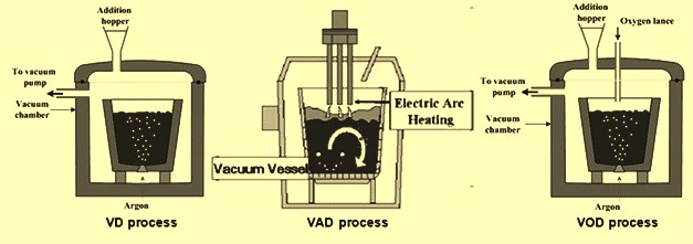
Fig 3 Schematics of ladle degassing processes
Vacuum degassing (VD) process
This is a simple ladle degassing unit with provisions for alloying additions. Here, vacuum is created through a vacuum pumping system. Pressure as low as 0.5 mm Hg is created. The process is capable of (i) homogenization of liquid steel bath with regard to both temperature and composition, (ii) fine adjustment of chemistry, and (iii) improved de-oxidation and reduction in H2, N2, and O2 contents. De-sulphurisation is a big problem for heats directly processed through VD unit from primary steelmaking furnace. However, the problem can be sorted out through ensuring reduced slag in the ladle before sending the heat to VD unit and enhanced desulphurisation is caused by slag-metal mixing.
Vacuum arc degassing (VAD) process
Vacuum arc degassing (VAD) process is a tank degassing process with electrodes added for the purpose of reheating the liquid steel. This is a single unit process in which the ladle sits in a vacuum tank and is stirred by inert gas through porous plug at the bottom with provision for heating through electrodes and alloying additions. After addition of lime to the liquid steel in the ladle, arcing is carried out at a pressure of 250 mm Hg to 300 mm Hg to raise the temperature and fuse the lime followed by short duration degassing, additions for chemistry adjustment and deep degassing to pressures as low as 1 mm Hg. Ar stirring is continued in all the operational steps and the adjustment of flow rate is done for different operations being carried out during the VAD process. The heating rate is around 3 deg C/min to 4 deg C/min and during heating the rate of Ar flow is kept on the lower side. In this system, under vacuum, C-O2 reaction and C-Al2O3 reaction under the high temperature arc are of great help in achieving low O2 content without any solid reaction product. H2 levels as low as 1.5 ppm are achieved caused by intense mass transfer by Ar and low partial pressure of H2 because of dilution of liberated carbon monoxide (CO). The main advantage of this process is the high degree of desulphurisation as high as 80 % for production of steels with sulphur levels as low as 0.005 %. VAD is now a widely used process for the production of clean steel.
ASEA – SKF process
It is a process which possesses integrated group of treatment units usually consisting of separate de-slagging, arc heating and vacuum treatment units. Here, slag is removed by re-ladling to prevent re-phosphorization after which ferro-alloy addition is carried out. Arc heating is done to raise temperature for compensating the cooling effect of the alloying additions followed by degassing in a vacuum atmosphere for reducing the O2 content and de-hydrogenation for achieving H2 contents as low as 1.5 ppm. The method involves application of electro-magnetic stirring which helps in floating inclusions and result in production of clean steels. Presently, ASEA-SKF units have incorporated basic inert gas stirring to enable desulphurisation.
Vacuum oxygen de-carburization (VOD) process
VOD process is a tank degassing unit which is additionally equipped with an O2 blowing lance. This additional supply of O2 can be used for the production of extra low C stainless steel grade (forced decarburization) or for chemical heating of the liquid steel in conjunction with Al/Si (silicon) additions (VD-OB process). The vacuum pump is designed accordingly, having a higher capacity in order to cope with the increased off-gas volume.
VOD process is considered to be an important vacuum process for production of stainless steel. It is mainly suitable for special stainless steels which require the very low value of C, N2, and H2 levels. In this process, the ladle is placed in vacuum chamber and there is a provision for O2 lancing through vacuum tight gland and alloying additions. Basically, the process involves preferential oxidation of carbon over Cr leading to minimum losses of Cr.
Because of reduced freeboard available in the ladle, the initial C content of the liquid steel is to be as low as 1 %. Here, O2 injection is carried out at 100 mm Hg to 250 mm Hg. Si is oxidized followed by C. De-carburization occurs through start of co bubbling determined by initial temperature and Si content of the liquid steel. Constant rate of de-carburization occurs depending on the O2 flow rate. The CO/CO2 ratio is monitored and at a bath C content of 0.08 %, it increases rapidly. Beyond this limiting C percentage, de-carburization rate falls independent of O2 flow rate with simultaneous Cr oxidation. O2 lancing is ceased and the vessel pressure is reduced and Ar stirring is carried out further to the reaction between the dissolved O2 and the remaining C. It has been reported that through vigorous stirring C can be reduced to levels of 0.005 % and total C + N2 less than 0.015 % are achieved.
The refining sequence in general is controlled by combination of variation in O2 flow rate, the lance tip – bath surface distance, control of vacuum pressure and the Ar flow rate. Addition of sufficient amount of lime and Al helps in excellent de-sulphurisation of the liquid steel.
Vacuum pump system
Vacuum pump system is the driving force for the vacuum degassing processes for liquid steel. For creating vacuum, there are three basic types of vacuum pump systems which can be used. Each has its own advantages and disadvantages. These are (i) steam ejectors with necessary condensation stages, (ii) steam ejectors in combination with water ring pumps, and (iii) dry mechanical pumping systems. Steam jets work on a constant mass flow basis, while water ring vacuum pumps work on a constant volume basis. Used together, an economic break-even point can be reached to take advantage of the best characteristics of each. Vacuum pumping system with steam ejectors as well as with steam ejectors along with water ring pumps are shown in Fig 4.
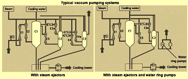
Fig 4 Typical vacuum pumping systems
Several factors play a role in the selection of the vacuum pump systems. These are given below.
- The quantity of dissolved gases to be removed. Absolute pressure, steel chemistry, and Ar flow rate all affect the rates at which the gases are removed by the vacuum pumping system.
- The load at system design pressure in ‘dry air equivalent’.
- The load the system needs to meet at different pressures (if required by out gassing system).
- The system volume involved.
- The process time requirement required to go from atmosphere to deep vacuum.
- The final absolute pressure of the system. This determines the number of stages which are needed.
- The quantity of Ar required. This determines the agitation energy and the rate of dissolved gas removal.
- The in-leakage rate of air into the system.
- The steam pressure and temperature in case of steam ejectors systems.
- The cooling water temperature in case of steam ejector systems.
- The cost of steam and electricity
Each degassing system is to be designed to meet the specific requirements of the vacuum degassing process.

Leave a Comment