Fundamental of valves and their types
Fundamental of valves and their types
Valves are mechanical devices. They are basic elements with which the flow of fluids and pressure within a system can be regulated. They are mainly used to control the direction of fluid flow as well regulate the amount fluid flowing through a particular system or a process. They perform any of the following functions.
- Starting and stopping or isolating fluid flow. This corresponds to on and off functions.
- Controlling or varying (throttling) the amount of fluid flow by change of direction or restriction. This corresponds to volume functions.
- Checking the flow or controlling the direction of fluid flow and preventing backflow. This corresponds to directional functions.
- Regulating downstream system or process pressure
- Relieving component or piping over pressure
There are many valve designs and types that satisfy one or more of the functions identified above. A multitude of valve types and designs safely accommodate a wide variety of industrial applications.
Regardless of type, all valves have the following basic parts: the body, bonnet, trim (internal elements), actuator, and packing.
Valves work by creating a partial or complete obstruction in the flow of fluids. The formation of obstruction can be formed manually or by injecting automatic elements in the system. A manual valve is generally controlled by handles, pedals or levers.
An automatic valve is generally driven by pressure changes (pneumatic valves), although there can be other versions as well, where they are driven by electrical signals (solenoid valves). Automatic valves are more common nowadays, except for operations which require human judgement.
The regulation is accomplished by the varying resistance that the valve introduces into the system as the valve is stroked. As the valve modulates to the closed position the system pressure drop shifts to the valve and reduces the flow in the system.
Because of the diversity of the types of systems, fluids, and environments in which valves must operate, a vast array of valve types have been developed. Isolating valves also called ‘block valves’. Possible valve choices for isolating service are gate valves, ball valves, butterfly valves and plug valves. Possible choices for control and regulating service are globe valves, butterfly valves, ball valves and plug valves. Under check valves swing check are most common. Many globe valves can be made ‘stop check’ or non-return types. Safety and pressure relief valves are special on/off valves. They are designed to open and relieve excess pressure, re-close after normal conditions are restored, and function when normal operating controls fail. They are not designed to control normal operating pressure. These valves are most critical valve in pressurized systems and they are often referred to as PRVs (pressure reducing valves). Other common types of valves are the diaphragm valve, and pinch valve. Each type of valve is normally designed to meet specific needs.
Some valves are capable of throttling flow while other valve types can only stop flow. There are valves which work well in corrosive systems while some other valves handle high pressure fluids. Each valve type has certain inherent advantages and disadvantages. Understanding these differences and how they affect the valve’s application or operation is necessary for the successful operation of a facility.
Although all valves have the same basic components and function to control flow in some fashion, the method of controlling the flow can vary dramatically. In general, there are four methods of controlling flow through a valve as given below.
- Move a disc, or plug into or against an orifice (for example, globe or needle type valve).
- Slide a flat, cylindrical, or spherical surface across an orifice (for example, gate and plug valves).
- Rotate a disc or ellipse about a shaft extending across the diameter of an orifice (for example, a butterfly or ball valve).
- Move a flexible material into the flow passage (for example, diaphragm and pinch valves).
Each method of controlling flow has characteristics that make it the best choice for a given application of function.
Types of valves
Some of important types of valves are described below.
- Gate valves – They are generally used in systems where low flow resistance for a fully open valve is desired and there is no need to throttle the flow. Gate Valves are designed to operate either in fully open or fully closed position. Because they operate slowly they prevent fluid hammer, which is detrimental to piping systems. There is very little pressure loss through a gate valve. In the fully closed position, gate valves provide a positive seal under pressure. However, under very low pressure, i.e. at 0.35 kg/sq cm light seepage is not be considered abnormal with this kind of valve.
- Globe valves – These valves are used in systems where good throttling characteristics and low seat leakage are desired and a relatively high head loss in an open valve is acceptable. Globe valves, as is the case with all valve designs, have both advantages and disadvantages. Like a gate, they close slowly to prevent fluid hammer. These valves can throttle the flow and they will not leak under low pressure when they are shut off. Flow and pressure control valves as well as hose bibs generally use the globe pattern. The disadvantage of this design is that the ‘Z’ pattern restricts flow more than the gate, ball, or butterfly valves.
- Ball valves – These valves allow quick, quarter turn on-off operation and have poor throttling characteristics. These valves are also designed to be operated fully open or fully closed with any liquid containing particles that could scratch the ball. Many people use them successfully for throttling clear water. Ball valves have low pressure drops, open and close quickly, are simple, and are trouble free. With the development of Teflon seals, ball valves have grown in popularity. Opening or closing a ball valve too quickly can cause fluid hammer.
- Plug valves – These valves are often used to direct flow between several different ports through use of a single valve. Like the gate valve, a plug valve has an unobstructed flow, yet requires only a 90 degree turn to open it. It also requires very little headroom. Stem corrosion is minimal because there are no screw threads. Almost all plug valves are now furnished with an elastomer coated plug. These valves seals off drip tight. Plug valves are available in much larger sizes than ball valves and are highly suitable for use in wastewater plants.
- Butterfly valves – These valves provide significant advantages over other valve designs in weight, space, and cost for large valve applications. Butterfly valves, like ball valves, operate with a 1/4 turn. These valves have center-hinged swinging disc. Low pressure and low temperature designs are resilient seated, usually rubber lined. These valves can be used for blocking or regulating. High performance types of valves are metal seated. These valves are often double and triple ‘offset’ to reduce closure torque. They are generally used for handling large flows of gases or liquids, including slurries, but should not be used for throttling for extended periods of time. They are also very compact relative to flanged gate and ball valves. These valves are relatively expensive to repair.
- Diaphragm valves – Diaphragm valves are linear motion valves that are used to start, regulate, and stop fluid flow. The name is derived from its flexible disk, which mates with a seat located in the open area at the top of the valve body to form a seal. These valves are used in systems where it is desirable for the entire operating mechanism to be completely isolated from the fluid.
- Pinch valves – The relatively inexpensive pinch valve is the simplest in any valve design. It is simply an industrial version of the pinch cock used in the laboratory to control the flow of fluids through rubber tubing. Pinch valves are suitable for on-off and throttling services. However, the effective throttling range is usually between 10 % and 95 % of the rated flow capacity. Pinch valves are ideally suited for the handling of slurries, liquids with large amounts of suspended solids, and systems that convey solids pneumatically. Because the operating mechanism is completely isolated from the fluid, these valves also find application where corrosion or metal contamination of the fluid might be a problem.
- Check valves – These valves are automatically open to allow flow in one direction. Check valves are designed to prevent the reversal of flow in a piping system. These valves are activated by the flowing material in the pipeline. The pressure of the fluid passing through the system opens the valve, while any reversal of flow will close the valve. Closure is accomplished by the weight of the check mechanism, by back pressure, by a spring, or by a combination of these means. The general types of check valves are swing, tilting-disk, piston, butterfly, and stop. A stop check valve is a combination of a lift check valve and a globe valve and incorporates the characteristics of both.
- Needle valves – Needle valves are used to make relatively fine adjustments in the amount of fluid flow. The distinguishing characteristic of a needle valve is the long, tapered, needle like point on the end of the valve stem. This ‘needle’ acts as a disk. The longer part of the needle is smaller than the orifice in the valve seat and passes through the orifice before the needle seats. This arrangement permits a very gradual increase or decrease in the size of the opening. Needle valves are often used as component parts of other, more complicated valves. For example, they are used in some types of reducing valves.
- Safety and relief valves – are used to provide automatic over pressurization protection for a system. Relief and safety valves prevent equipment damage by relieving accidental over pressurization of fluid systems. The main difference between a relief valve and a safety valve is the extent of opening at the set point pressure. A relief valve gradually opens as the inlet pressure increases above the set point. A relief valve opens only as necessary to relieve the over-pressure condition. A safety valve rapidly pops fully open as soon as the pressure setting is reached. A safety valve will stay fully open until the pressure drops below a reset pressure. The reset pressure is lower than the actuating pressure set point. The difference between the actuating pressure set point and the pressure at which the safety valve resets is called blow down. Blow down is expressed as a percentage of the actuating pressure set point. Relief valves are typically used for incompressible fluids such as water or oil. Safety valves are typically used for compressible fluids such as steam or other gases. Safety valves can often be distinguished by the presence of an external lever at the top of the valve body, which is used as an operational check.
A few types of valves are shown in Fig 1
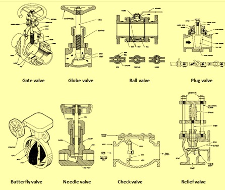
Fig 1 A few types of valves
Leave a Reply to Anonymous Cancel Reply