Flanges and Their Types
Flanges and Their Types
In a steel plant there are large numbers of pipe networks. These pipe networks use a large number of flanges. These flanges are made of carbon steel and alloy steel and are of various types, shapes and sizes.
A pipe flange is a disc, collar or ring that attaches to pipe with the purpose of providing increased support for strength, blocking off a pipeline or implementing the attachment of more items.
Flanges are piping components used for connecting pipes with other piping components like valves, specialties, instrument items like orifice, flow meters etc. They are also used to connect pipes with pumps and other equipment to form a pipework system. They facilitate the dismantling and periodic maintenance of piping components, pumps and equipment etc. They provide easy access for cleaning, inspection or modification.
Flanges form semi-permanent connections to join parts which are light enough to be moved with available equipment or which cannot be welded due to heat sensitivity or replacement needs. They are usually welded or screwed into such systems and then joined with bolts. A flanged joint is composed of three separate and independent although interrelated components namely (i) the flanges, (ii) the gaskets, and (iii) the fasteners. Gasket is normally inserted between the two mating flanges to provide a tighter seal.
There are numerous types of flanges available. The type and material of a flange to be used is dependent on the service duty of the line.
Flanges are either custom built with dimensions provided by the customer or they are manufactured according to a specification as per various national and international standards. Flanges of different standards are normally not interchangeable and hence are not usually joined. If necessary to do so, they are to be checked to ensure the compatibility of the mating flanges. Further many of the flanges in each standard are divided into ?pressure classes?, allowing flanges to be capable of taking different pressure ratings. These ?pressure classes? also have differing pressure and temperature ratings for different materials.
Flange types
Flange type is defined by the way in which the flange is attached to the pipe. The following are the available flange types (Fig 1).
Weld neck flanges
Weld neck flanges have a long, tapered hub between the flange ring and the weld joint. This hub provides a gradual transition from the flange ring thickness to the pipe wall thickness thereby decreasing the discontinuity and increasing the strength.
The weld neck flange is butt-welded to the pipe. This flange comes in two types, regular and long. The hub of the weld neck is designed to reduce the stress at the base of the flange. Regular weld neck flanges are used with butt weld fittings and long weld neck flanges are usually used with equipment and vessel nozzles. A long weld neck flange is rarely used with pipe. Both types of flanges are bored to match the inside diameter of the pipe or fitting to which it will be welded to. The matching of the bore reduces turbulence and erosion inside the pipeline
This flange is circumferentially welded into the system at its neck which means that the integrity of the butt welded area can be easily examined by radiography. Besides radiography the butt weld can be inspected by ultrasonics as well as magnetic particle inspection or dry particle inspection during fabrication. There is therefore a high degree of confidence in the integrity of the weld. A butt weld also has good fatigue performance and its presence does not induce high local stresses in the pipework.
Weld neck flanges are favoured in critical applications. They are preferred for extreme service conditions such as high temperature, high pressure, hazardous fluids, wide fluctuations in pressure and temperature and sub-zero temperature. They are suitable where shear impact and vibratory stresses apply.
Socket weld flange
Socket weld flanges are similar to a slip-on flanges, except they have a bore and counter bore. The counter bore allows the pipe to fit into the socket/counter bore. The bore of the flange is the same diameter as the inside of the pipe. Since the bore of the pipe and that of the flange is the same the flange provides good flow characteristics.
Socket weld flanges are often used on high pressure, hazardous duties but their usage is usually limited to a nominal pipe size of 40 mm. The pipe is fillet welded to the hub of the socket weld flange. Radiography is not practical on the fillet weld and correct fit-up and welding is therefore crucial. The fillet weld is normally inspected by magnetic particle inspection or dry particle inspection.
Slip on weld flange
Slip-on weld flanges are designed to slip over the outside of pipe, long-tangent elbows, reducers, and swages and then fillet welded. The flange has poor resistance to shock and vibration. The flange is easier to align than welding neck flange. This flange is ideal for low pressure applications since the strength when under internal pressure is about one third that of a weld neck flange.
Slip-on flanges are easy to use in fabricated applications. They are typically used for low hazard moderate services where pressure fluctuations, temperature fluctuations, vibrations and shock are not expected to be severe such as fire water service, cooling water service etc. Since the pipe is ?double-welded? both to the hub and the bore of the flange, hence radiography is not practical. Normally magnetic particle inspection or dry particle inspection methods are used to check the integrity of the weld.
Where specified, the slip-on weld flanges are used on pipe sizes greater than 40 mm with a preference for the socket weld flange for sizes up to and including 40 mm.
The strength of slip-on flange is around 2/3 times to that of weld neck flange. The fatigue life of this type of flange is 1/3 that of a weld neck flange. This flange is widely used because of its greater ease of alignment in welding assembly and because of its low initial cost.
Lap joint flange
Lap joint flange is used with a lap joint stub end fitting and comprised of a hub or ?stub end? welded to the pipe and a backing flange or capped flange which is used to bolt the joint together. This means the stub end always makes the face. It is similar to a slip-on flange, but with two differences. The radius and the flat face, both allow the flange to secure against the stub end fitting. This is useful where alignment of bolt holes is difficult, such as with spools to be attached to flanged nozzles of the vessels.
This type of flanged joint is typically found on high alloy pipework. An alloy hub with a galvanized steel backing flange is cheaper than a complete alloy flange. The flange has a raised face and sealing is with a flat gasket.
The lap joint flange is favoured in low pressure applications because it is easily assembled and aligned. It is not suitable where high external of heavy loads are present. The principal advantage of these flanges is that the bolt holes are easily aligned, and this simplifies the erection of the vessel. They are also useful in cases where frequent dismantling for cleaning or inspection is required. Its fatigue life is about 10 % of the fatigue life of the weld neck flanges.
Swivel ring flange
In the swivel ring flange, a hub is butt welded to the pipe as in the case of the lap joint flange. A swivel ring sits over the hub and allows the joint to be bolted together. Swivel ring flanges are normally found on sub-sea services where the swivel ring facilitates flange alignment. The flange is sealed using a ring type joint (RTJ) metal gasket.
Threaded flange
Threaded flange is either threaded or screwed. The flange is similar to a slip-on flange, but has internal threads. It is normally used to connect other threaded components in low pressure and non-critical applications. This type of flange is not used where temperature or stress is very high.
The threaded or screwed flanges are used on pipelines where welding cannot be carried out.
Blind flange
Blind flange does not have a bore. It is sometimes referred to as a blanking flange. This flange is used to blank off pipelines, valves and pumps. When used at the end of a pipe or fitting, it provides an easy to open access for further extension of the pipe. It can also be used as an inspection cover.
The blind flanges are used to close the ends which need to be reopened later. The blind flange and its bolts are stressed more than any other flange.
Ring joint facing flange
Ring joint facing flange is also known as RTJ flange. It is normally used for a leak-proof connection in high pressure applications. The flange has a hexagonal groove sealing surface and is fitted with a metal ring that is compressed in a groove.
This jointing method can be employed as on weld neck, slip-on and blind flanges.
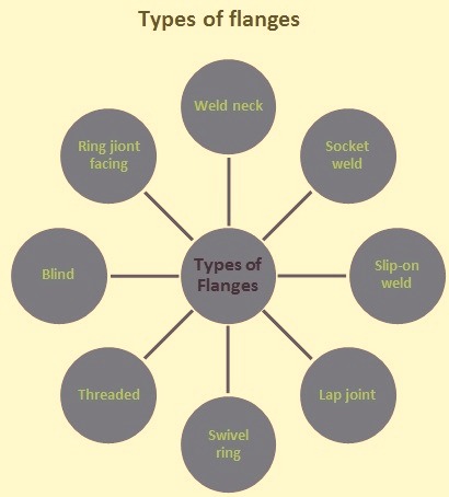
Fig 1 Types of flanges
Flange facing types
There are different types of flange faces. These are given below.
- Flat face – Typically flat face is used on pump facings or on fiberglass flanges where the torque of compressing the gasket can damage the flange body. Their principal use is to make connections with cast iron flanges. They are mainly used for rubber lined equipments of chemical plants. They are also used for equipments operating under low pressure. Since the width of the gasket is more, the gasket seating force is more.
- Raised face – The raised face is the most common used flange face. It is called raised face because the gasket is raised 1.5 mm to 6 mm above the bolt circle face. The flange facings are machine finished to meet the requirements of the standards and has unconfined gasket. They are suitable for average service conditions. For severe service involving high pressure, high temperature, thermal shock, or cyclic operations, this type of flange facing is normally not satisfactory.
- Ring type joint – Ring type gaskets are to be used on the flanges with this type of facing. This type of facing is used in severe service conditions and for hazardous fluids. It is used in petroleum, petrochemical and high pressure gas pipe work and equipments. Since close tolerances and high standards of machining are required, as a result this type of flange facing is seldom used for flange diameters larger than 900 mm. The main disadvantage of this type of facing is the high cost of manufacturing. It is the most expensive face
- Tongue and groove facing – This type of facing has fully confined gasket. Groove is usually not over 1.5 mm wider than tongue. Gasket dimensions match tongue dimensions. The flange is less subject to erosive and corrosive contact with the vessel. Since the tongue is more likely to get damaged than the groove, it is normally attached to the part which can be easily removed from the vessel.
- Male and female facings – These facings have the advantage of confining the gasket and thereby minimizing the possibility of blowout of the gasket. The two mating flanges are not identical. For this reason these flanges are not widely used on pipe-line connections as are the raised face flanges. They offer no protection against forcing the gasket into the vessel. Recessed outer diameter (OD) normally is not more than 1.5 mm larger than the OD of the male face. Joint is to be pried apart for disassembly.
Flange specification and identification
A flange is normally specified by the following information.
- Type and facing such as weld neck, ring type joint facing or socket weld, raised facing etc.
- Nominal pipe size usually required for all flanges.
- Flange pressure class usually required for all flanges
- Flange standard such as ANSI, API, ASME, EN, JIS, IS etc.to which the flange conforms to.
- Specification of the material of the flange
- Pipe schedule only for weld neck, socket weld, lap joint and swivel ring flanges where the flange bore must match that of the pipe.
There are available flange sizes and grades for all standard pipe wall thicknesses and pressure ratings.
Flanges are normally manufactured in several pressure ratings. The ratings can be expressed in different ways but mean the same thing. Each class of flange can handle more pressure than the previous class because of its construction. The higher the class is, the thicker the metal is. Thus a higher pressure can be handled. There are numerous factors which can affect the pressure capability of a flange, such as the type of metal that is used. But basically when pressure goes down, the temperature goes up and vice versa.
For the identification of the flange, normally, the flange specification is hard stamped on the flange. All flanges are usually stamped for identification on the outside diameter of the base for easy identification.
In the case of a flange which is under use for a long time, the marking may not be legible on the flange and it is then necessary to identify the flange by visual observation and physical measurement. Visual observation is required to identify the type of flange and type of gasket used while the physical measurement is needed to identify the nominal bore and the class of the flange. The number of stud bolts, stud bolt diameter, stud bolt pitch circle diameter (PCD) and the flange thickness need to be checked. These measured figures are then compared with standard flange data for the identification of the flange.
The specification of material from which the flange is produced is usually specified by the flange standard.
The flange face finish is determined by the standard used and measured as an arithmetical average roughness height (AARH). Generally the flange face finishes are of the following types.
- Cold water – It has a mirror like finish. This is made with a wide tool at a high speed which gives a finished surface much like a ground surface. When a surface has this type of finish it is normally used metal to metal, not with a gasket. It is seldom used in the oil, chemical or related industries.
- Concentric serrated – A 90 degree inclined angle tool is used to make the grove. It makes a grove 0.4 mm deep and 0.2 mm apart in a concentric circle.
- Smooth – This can be made with several different types of tool shapes. No tool markings are to appear to the naked eye on the surface. The roughness of the finish is from 5 to 10 micro millimeters.
- Spiral serrated – This is similar to a stock finish but the difference between them is the way the grove is made. A 90 degree inclined angle tool is used to make the grove. It makes a grove 0.4 mm deep and the feed is 0.2 mm.
- Stock – The surface is created by a continuous spiral groove. The roughness of the finish is from 5 to 20 micro millimeters and is cut with a tool with an approximately 1.5 mm or larger radius.
There are many flange designs. Some flanges are manufactured as per formal standards while some flanges are best described as conforming to manufacturer?s standards that is, two flanges from one manufacturer will mate, but they may not if from different manufacturers.
Commonly used flange designs have a soft gasket squeezed between harder flange surfaces to form a leak-free seal. The various gasket materials are rubbers, elastomers (springy polymers), soft polymers covering a springy metal (e.g., PTFE covered stainless steel), and soft metal (copper or aluminum). Each flange design has merits.
There are many different flange standards to be found worldwide. To allow easy functionality and inter-changeability, these are designed to have standardized dimensions. In most cases flanges are not interchangeable if they are made as per different standards (e.g. an ANSI flange will not mate against a JIS flange). Further many of the flanges in each standard are divided into “pressure classes”, allowing flanges to be capable of taking different pressure ratings. Again these are not generally interchangeable. These ?pressure classes? also have differing pressure and temperature ratings for different materials.
Leave a Reply to Anonymous Cancel Reply