Air Blast System for Blast Furnace
Air Blast System for Blast Furnace
A blast furnace (BF) produces liquid iron (hot metal) by the reduction of ore burden with reducing gases. The reducing gases are produced by the reaction of oxygen with coke and coal. This oxygen is part of enriched hot air blast which is blown and distributed at the bottom of the BF through the straight pipes, blowpipes and the tuyeres. This set is connected to the main bustle pipe. The volume of air which is enriched with oxygen and blown for the process in the BF to take place is provided by the air blowers. These air blowers take the air from atmosphere and compress it to the required pressure. This compressed air which is at about up to 200 deg C temperatures after compression is enriched with oxygen and blown into the hot stoves where the temperature is raised up to 1.200 to 1250 deg C. This hot blast air is then taken to bustle pipe through hot blast main. Air blast systems of modern high capacity blast furnaces operate with blast temperatures of up to 1350 deg C and blast pressures up to 5 kg/sq cm (g). The whole process is typically shown in Fig 1.
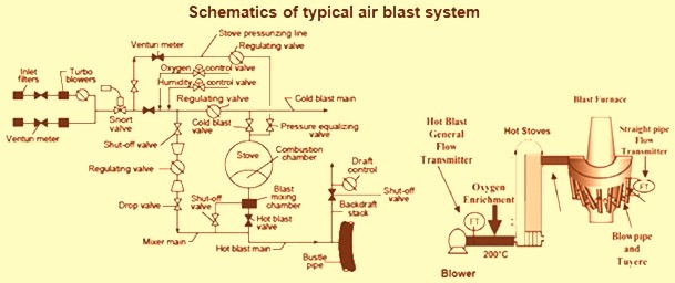
Fig 1 Schematics of typical air blast system
The main components of an air blast system of a blast furnace consist of (i) air blower, (ii) cold blast main, (iii) hot blast stove along with its combustion system, (iv) hot blast main, (v) bustle pipe, (vi) blow pipes and tuyeres known as tuyere stocks, (vii) set of valves, and (viii) control instruments.
The air blower is the first equipment in the air blast system. It is located in the blower house and is meant for providing cold air blast to the hot blast stoves at the desired constant flow volume and pressure. Hence surge protection control is a very important control for a blast furnace air blower. Generally two numbers of air blowers are provided for a blast furnace. It draws the volume of air from the atmosphere and compresses it to the needed pressure and blows it into cold blast main. The compressed air is usually at 150 deg C to 250 deg C, which is the temperature resulting from the heat of compression at the air blower. The air blowers are either steam turbine driven or electric motor driven. The air blower is required to be operated to meet the air flow conditions which in turn are determined by the operating condition of the blast furnace. Also they need to have a very high level of reliability since the performance of the blast furnace depends a lot on the performance of the blower.
For generating the blast air, most blast furnaces are equipped with centrifugal turbo-blowers provided with three or four stages. For some of the very large blast furnaces, two blowers operate in parallel. However, with very large blast furnaces axial blowers can be used more efficiently. Modern blast furnaces have either axial or axial radial isothermal compressors which are designed to handle large volume of air flows within relative small casings while maintaining excellent efficiencies.
Cold blast main connects the air blower and hot blast stoves. It is normally not lined since the temperature of the cold blast is normally between 150 deg C to 250 deg C. However in some furnace as energy saving measure cold blast line is insulated. At the stove end of the cold blast main there are the cold blast valves for the stoves and the mixer line which is equipped with a butterfly valve. To maintain a constant hot blast temperature to the blast furnace, a thermocouple in the hot blast main controls this butterfly valve in the mixer line and proportions the amount of air delivered to the stove and the amount bypassing it.
When a heated stove first goes on blast, the temperature of the heated air is much higher than the desired hot blast temperature, so a significant portion of the air must bypass the stove. As heat is removed from the stove and the temperature decreases, the mixer line butterfly valve must gradually close and force more of the air through the stove. In some automatic stove changing systems, the position of the regulating valve is used as the signal that initiates a stove change.
The cold blast main is also equipped with a snort valve, usually located near the blast furnace which is opened when it is necessary to decrease the blast pressure rapidly. This discharges the cold blast air to the atmosphere and keeps a positive pressure on the cold blast line so that gas from the furnace cannot travel back to the air blower. Because of the rapid discharge of air when the snort valve is opened, it is normally equipped with a muffler.
At plants where the air blast is enriched with oxygen, the oxygen can be added at atmospheric pressure to the inlet of the turbo-blower or it can be added under pressure in the cold blast main. Moisture is added in the cold blast main when it is required for blast moisture control.
Hot blast stove is a facility to supply continuously the hot air blast to a blast furnace. Before the air blast is delivered to the blast furnace tuyeres, it is preheated by passing it through regenerative hot blast stoves which are heated primarily by combustion of the blast furnace top gas (BF gas). In this way, some of the energy of the top gas is returned to the blast furnace in the form of sensible heat. This additional thermal energy returned to the blast furnace as heat reduces the requirement of blast furnace coke substantially and facilitates the injection of auxiliary fuels such as pulverized coal as a replacement for expensive metallurgical coke. This improves the efficiency of the process. Hot blast stoves of a modern blast furnace have the following characteristics.
- Achievement of high efficiency combustion – Achievement of high efficiency combustion even in the operation with only blast furnace gas.
- Smaller heat radiation from the stove body.
- Low construction costs.
- High stove service life -Expected service life of a modern stove is around 40 years
- Complete elimination of stress corrosion cracking.
- Low concentration of non-combusted CO above the upper surface of checker bricks.
Most blast furnaces are equipped with three hot blast stoves, although in some blast furnaces there are four stoves. The stoves are tall, cylindrical steel structures lined with insulation and almost completely filled with checker bricks where heat is stored and then transferred to the air blast. Each stove is about as large in diameter as the blast furnace, and the height of the column of checkers is about 1.5 times as tall as the working height of the blast furnace. At the modern blast furnaces, the relation of the stove size to the furnace size is even larger. The hot blast stoves have been separately described in the article http://www.ispatguru.com/generation-of-hot-air-blast-and-hot-blast-stoves/.
Hot air blast is delivered from the hot blast stoves to the blast furnace through a large, refractory-lined duct called the hot blast main. A consistent high temperature of the hot air blast is critical for the efficient operation of the blast furnace. The designs of the hot blast mains along with the bustle pipe are to address system movements and residual expansions to give trouble free operation. The designer of the blast furnace hot blast main faces several unique challenges. The hot blast main is typically a large diameter pipe subject to a number of thermal expansion components. The expansion joint system must be designed to accommodate thermal movements in the X, Y and Z directions of the stove branch connections, main and bustle pipe. Thermal movements are due to variations in skin temperature caused by the media as well as variations in the temperature of tie rods and structures due to changes in ambient conditions. Consideration must also be given to the forces and movements imposed on the stove connections and structures as well as stresses in the hot blast piping system. Finally, the expansion joints must operate over the lengthy blast furnace campaign with minimal requirement of the maintenance.
There are a large number of valves and fittings which are needed for the air blast system. Some of the major valves are given below.
- Cold blast valve – It is intended for the complete separation of the blast furnace stove from the cold blast main. It is installed on the horizontal cold blast main near the stove.
- Snort valve – It is installed in the cold blast line main. The valve has a blow off device. This is used to regulate the cold blast quantity which is being supplied to stoves, without creating the back pressure on the blower, as the excess air is blown away through a blow off device which is mechanically interlinked with the main valve for proportionate opening / closing.
- Hot blast valve – It is intended for the separation of the hot blast stove of the blast furnace from the hot blast main, when operating the stove in the mode ‘at the heating’ or at the complete separation from the blast furnace. This valve is installed in the horizontal hot blast main near the stove.
- Atmospheric valve – It is intended for releasing the stove of the blast furnace from the chimney.
- The gas throttle valve – It is designed for the gas control supplied to the hot blast stove gas burner and the full release of the conduit gas burner as at the normal operation and in case of failure of power supply. It is installed on the vertical section of the gas conduit.
- Mixing throttle valve- It is intended for adjusting cold blast rate. It is mounted on the vertical section of cold blast main near the stove.
- Chimney valve – It is intended to separate the blast furnace stove from the chimney.
- Separator valve – It is designed for fast overlap of the mixing air-line section in case of stop of the blast supply into the furnace. It is installed on the horizontal section of the cold blast mixing air-line.
The large diameter circular pipe that encircles the blast furnace at above mantle level is called the bustle pipe. It is used to distribute the hot blast air from the hot blast main into the furnace through a number of nozzles called tuyeres. The bustle pipe is internally lined with refractory to insulate and protect the outer steel shell from the high temperature air inside.
Tuyeres are small pipes that permit hot air from the bustle pipe to enter the blast furnace. They are special shaped nozzles through which hot air blast is injected into the blast furnace. They are made of copper and are usually water cooled since they are directly exposed to the furnace temperature. They are located all around the blast furnace like spokes on the hub of a bicycle wheel. Tuyere stock is the assembly of gooseneck, expansion bellow, connecting pipe, elbow, peep hole, blow pipe, fixing arrangement and tensioning device. The tuyere stocks, as the connection between the bustle pipe and the tuyere, adapts to the relative movements between the hot blast delivery system and the blast furnace.
The blowpipe, which connects the hot blast system to the tuyere, fits into a machined spherical seat at the base of the tuyere. The tuyere cooler and the tuyere are water cooled. On modern blast furnaces utilizing hot blast temperatures above 1150 deg C, the tuyere body water passages are designed to keep the water velocity above 20 m/sec and the tuyere nose water passages are designed to keep the water velocity above 28 m/sec to improve the rate of heat transfer. In some of the modern blast furnaces the nose of the blowpipe is also water cooled, although in most of the older furnaces this is not done. The fuel injection lance enters through the wall of the blowpipe and usually discharges the fuel slightly off the centerline and about 50 mm back from the nose of the blowpipe. Some blast furnaces are equipped with dual injection systems that have two openings in the blowpipe to facilitate multiple tuyere fuels. With the increased use of pulverized coal as a tuyere fuel, the injection lance placement is more critical to deter impingement on the inside of the tuyere and for better combustion of the coal. The blowpipe is held tightly against the tuyere by tension in the bridle rod, which connects the tuyere stock to the hearth jacket. The bridle spring on the end of the bridle rod allows limited motion as the blowpipe expands and contracts with changes in hot blast temperature. The blowpipe itself is an alloy steel tube lined with refractory material to prevent the metal from becoming too hot.
The main components of the tuyere stock are tightly connected with the polished tapered surfaces by means of the consequent close arrangement of the next part in the previous one. Thus the closed-fitted tapered surfaces provide the leak-tight integrity of the joint. A disturbance of operating heating cycle as well as any leakage of the one of the joints in the tuyere stock results in the burning of the construction elements and failures.
The tuyere, tuyere cooler and blow pipe operate in case of the heaviest temperature conditions. The tuyere cooler is placed in the breast of the furnace lining. The nozzle is coupled with the tuyere which is already 250 mm to 350 mm deep inside the body of the blast furnace.
The blow pipes are usually made of steel with coating from the special ceramic refractory lining. The tuyeres are made of copper. Previously art-type tuyeres were made of pressed copper sheets, wall thickness up to 8 mm. These days the tuyeres are usually made of centrifugally cast copper which ensures maximum operating life of the tuyere by means of the high manufacturability that provides the highest material homogeneity and the absence of micro pores. However this method is a bit more expensive than the tuyeres manufacturing by the means of vacuum casting. The latter is also sometimes applied in the production of the tuyeres and has a smaller conversion cost but there is a possibility of the slight non-homogeneity of material. Anyway, the casting method of the tuyeres production has almost superseded the application of the welded construction of the tuyeres due to its lower operating capacity despite of the lower production cost which is also associated with the hollow copper tuyere cooler casting. The tuyere cooler is also manufactured by means of casting and is made of copper (less often of bronze). It is mounted in the breast of the furnace lining and fixed through the flange with the additional welding to the hearth jacket.
The blast furnace tuyere is cooled by the water supplied at a rate of 15 – 25 cum/hour directly to the inner face of the tuyere. The heating temperature of the discharged cooling water is not to exceed 15 deg C. The pressure of the cooling water supplied to the face of the tuyere and tuyere cooler normally do not exceed 5 – 10 kg/sq cm. The use of the copper (with content min. 99.5% Cu) as the material of construction allows the removal of the heat effectively from the cone body of the tuyere operating in the extremely hot conditions.
At the back of the tuyere stock on the centre-line of the blowpipe and tuyere is a small opening through which a rod can be inserted for cleaning material out of the blowpipe. The opening is closed by a cap that can be opened when necessary but is gas tight when closed. In this cap, called a tuyere cap or wicket, there is a glass-covered peep sight that permits the operator to inspect the interior of the furnace directly in front of the tuyere. The upper part of the stock is connected by a swivel joint to the refractory lined nozzle of the gooseneck to which it is clamped by lugs and keys that fit into seats of hanging bars. Each gooseneck in turn is connected by flanges and bolts to a neck extending radial from the inside diameter of the bustle pipe. Tuyere stocks are designed for long service life and easy handling. The schematics of a typical tuyere stock arrangements are shown in Fig. 2.
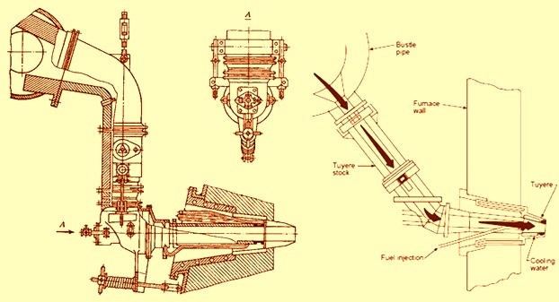
Fig 2 Schematics of typical tuyere stock arrangements
Leave a Comment